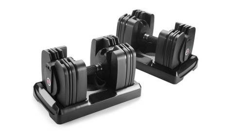
The Bowflex SelectTech 560® (ST560) is a “smart” dumbbell, a piece of exercise equipment with embedded sensors and processing to provide training feedback during your workout. The ST560 has an inertial measurement unit (IMU) to determine the motion of the device. Custom algorithms convert the raw motion data into information about the quality and speed of an exercise repetition, as well as allowing the device to count successful repetitions. This knowledge can be used to enhance the effectiveness of a workout, as well as providing a simple method to record the workouts completed. It can also make that information available to social media for informal competition with friends. Simplexity Product Development was heavily involved in the development of the ST560, owning the majority of the product firmware, as well as creating all of the data processing algorithms used to convert raw sensor data into the key exercise metrics.
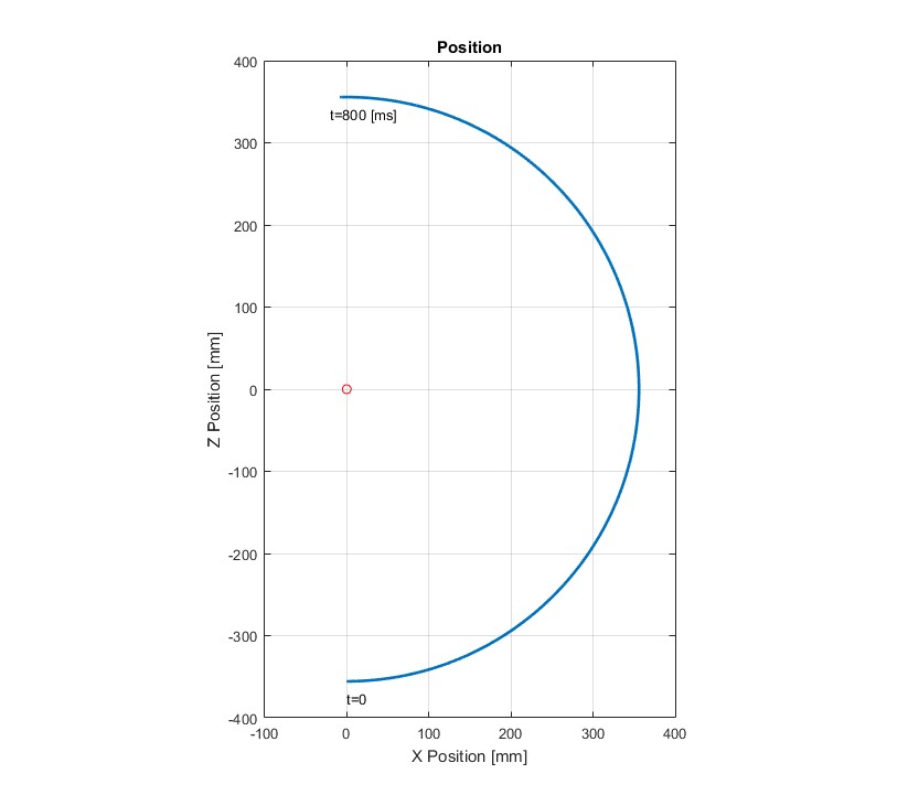
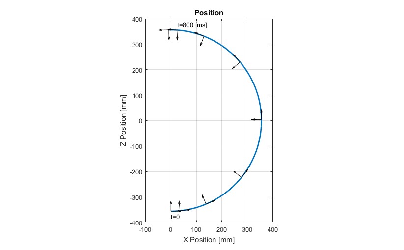
To explain exactly why a gyro is required, I’ll work through a simplified, two-dimensional example of the ST560 motion for the use case of a bicep curl. For this example, the motion we’re looking at is the rotation of the device about my elbow. My forearm is about 14” long (355 mm), and we’ll assume I do a rep that moves the dumbbell through 180 degrees of motion in just under one second, say 800 milliseconds (ms). The path for the analysis is shown in the image to the left.
A common misconception about products such as the ST560 and the HSI Loop CPR Training Device®, is that the only sensor required is an accelerometer. In order to create a viable IMU for measuring the position of a device in free space, it is critical to have both a 3-axis accelerometer and a 3-axis rate gyroscope.
At t=0, my arm is straight down. I rotate the dumbbell about my elbow (red circle), until it’s straight up at t=800 ms. To keep the motion simple, we’ll also assume that I accelerate for half the time (from t=0 to t=400 ms), then decelerate the other half (until t=800 ms).
The basic concept of the ST560 device is that we want to use a low cost accelerometer to measure this motion. To do so, we’ll measure the acceleration of the device in the X and Z directions, then integrate each of those signals twice to convert acceleration to position in each direction.
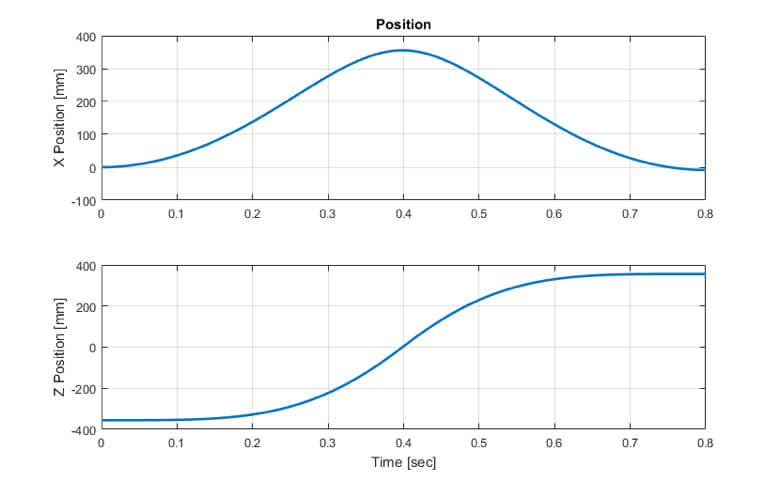
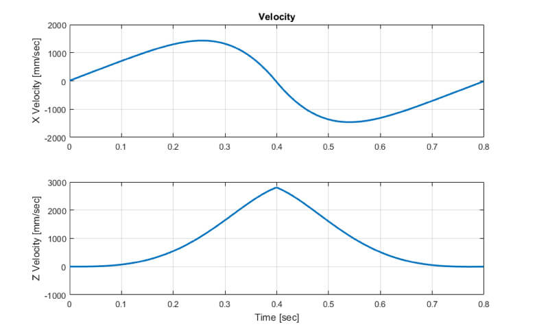
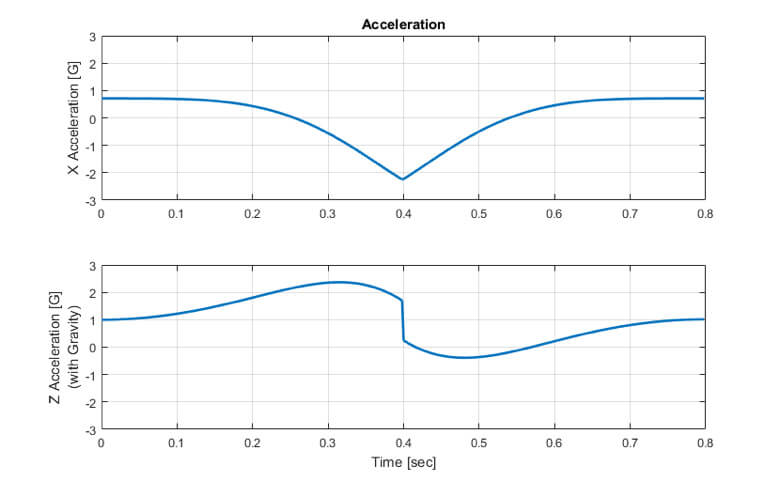
The next three charts show the position, velocity and acceleration of the device in both the X and Z directions. This gives us an initial look at the signals we’ll be dealing with from the accelerometer.
Note that I’ve added the offset due to gravitational acceleration to the Z axis acceleration data. The accelerometers will pick this up, so it’s important to add in.
If you think about the motion profile and remember your basic calculus (acceleration is the time derivative of velocity, velocity is the time derivative of position), these plots should make sense.
To get a position measurement, we just need to remove the gravitational acceleration from the Z accelerometer, integrate twice, and we have position. Sounds easy, right?
Here’s where things start to get tricky. The plots above all operate under the assumption that the accelerometer X channel measures X acceleration and the Z channel measures Z acceleration. What happens if the user rotates the device during motion? In fact, when I do a bicep curl, I tend to grip the dumbbell tightly, which causes the whole device to rotate in space to stay aligned with my arm. So, instead of the accelerometer channels staying aligned with the global reference frame used for the motion measurement, they actually measure in a rotating reference frame. The figure to the left shows how the X-Z axes rotate (small black arrows) during the motion.
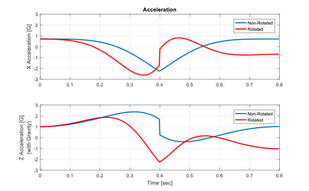
The figure below shows what the rotation does to the measured acceleration signals. The non-rotated measurements are shown in blue, while the rotated coordinate frame measurements are shown in red.
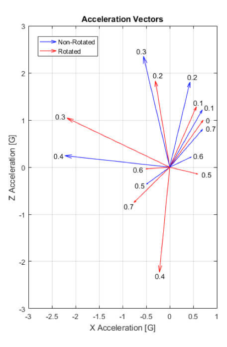
Clearly, these signals are very different. To look at the data in another way, the chart to the left shows the X-Z acceleration vector at snapshots every 100 ms during motion. Again, the blue arrows represent the non-rotated measurements, while the red arrows show the measurements from a rotated coordinate frame. The number near the arrow head is the time at which the measurement was taken. Note that at t=0, the arrows are on top of each other, as the local reference frame is aligned to the global reference frame.
As the plot clearly shows, as the device begins to rotate, the measured acceleration vector begins to rotate away from the value which we want to measure. If we were to integrate the rotated signals, we’d end up estimating a completely incorrect position. In fact, with the rotated signals, it’s not clear how to remove gravity from the measurement, as we know the gravity signal is not 100% in the Z measurement. How much of the 1 G of gravity should be subtracted from each of the measurements?
If we knew the exact motion ahead of time, we might have a chance. However, when we want to measure general motion for something like the ST560 dumbbell, we simply don’t have enough information.
ENTER THE GYROSCOPE!
As you’ve guessed by now, the solution to the problem is to introduce a gyroscope into the design. Rate gyros are standard components in low cost cell phone IMU’s. A rate gyro measures the rate of rotation of a body. Used in combination with an accelerometer, you theoretically have all of the information you need to estimate the orientation of the device. I say “theoretically” because there are few practical issues with these devices that complicate the situation. I’ll address those in a future blog posting. For now, we’ll assume we have ideal sensors.
Since I’ve conveniently thrown out a bit of reality, we can use the following high level algorithm for estimating the position of our device in 2D space. The steps go as follows:
- Whenever we’re not in motion, establish a baseline orientation.
- We can tell if we’re not in motion because the magnitude of acceleration vector will measure 1.0 while there will be zeros on the gyro signals for some period of time (you’ll have to figure out how long that time is for your application).
- When you’re not in motion, you’re only measuring gravity, so you know which way is down. For the 2D case, that’s all you need to establish your baseline orientation.
- From the baseline orientation, start integrating the gyro signals. The integrated gyro signal represents the orientation of the device.
- Measure the signals on the accelerometer channels.
- Using the orientation information from step 2, rotate the accelerometer data to align it to the global reference frame.
- Subtract off the gravity signal from the globally oriented Z acceleration signal.
- Integrate the globally oriented acceleration signals twice to get acceleration to get position.
EXTRA CREDIT!
In the analysis and algorithm above, we’ve made an implicit assumption that may be problematic in some designs. Everything I’ve presented so far assumes that the accelerometer is mounted at the center of mass of your device. If it’s not, then a pure rotation of the device will induce an acceleration at the sensor. For small mounting offsets and slow rotations, this signal may be fine to ignore. If not, you can use your gyro data to remove this error signal. The steps for doing that are:
- Read the rate gyro signals directly (no integration, we’re after rotation rate). Rotation rate is represented by ω.
- Estimate the angular acceleration by taking the time derivative of the gyro signals. This can be estimated by simply subtracting the previous reading from the current reading and dividing by the sample time. This angular acceleration is represented by α.
- Calculate the linear tangential and centripetal accelerations due to the rotation:
Acceltangental = α x r
where r represents the distance from the center of mass to the sensor.
Accelcentripital = ω2 / r
- Read the accelerometers.
- Subtract the acceleration values calculated in step 3 from the measured acceleration values before performing any rotations.
- Continue processing the signals as described previously.
For the Bowflex SelectTech 560, the use of both an accelerometer and a gyro was critical to generating usable position data. The algorithm described above formed the basis of our data processing. Of course, the realities of non-ideal sensors and operating in a three-dimensional environment complicated things significantly.
WHY YOU MAY NEED A COMPASS
As is usually the case, reality can be a bit more complicated. Gyro’s are not perfect sensors. They have both a DC offset and noise in the signal. When you integrate signals with those types of errors, the integrated value drifts. When using multiple sensors together, you need some sort of sensor fusion algorithm (I’ve used an extended Kalman filter when I’ve done it). The sensor fusion algorithm is responsible for “stabilizing” the gyro. That is, estimating the offset and noise and eliminating those so that the integrated signal doesn’t drift. The accelerometer provides a good signal for gravity which is used to estimate the correction factors to keep the integrated gyro signals level. However, there’s no information available to estimate the correction factors for a rotation about the gravity vector. That’s where sometimes we recommend using a compass. It provides that information, and can give a more fully stable orientation.

