Designing a quality product is hard work, but if you are a SolidWorks or other CAD user, check out the top 10 secrets that nobody taught us in school.
When we mechanical engineers create our designs, we rely heavily on our Computer Aided Design (CAD) tools, amazing and enormously complex masterpieces of modern software engineering and design. CAD tools automate many of the underlying tasks and let us focus on creating parts and assemblies that meet the functional demands outlined in the product requirements and the aesthetics of the industrial design. It is up to the talents and experience of the design engineer to ensure that those parts are producible. The designs that are not easy to produce are quickly weeded out and rarely see the light of day.
What is frequently overlooked is that good mechanical design is much more than simply reaching the finish line. Much like in software, quality mechanical design is every bit about the result and the process. The level of automation built into our amazing design tools makes it possible, even easy, to create a beautiful, functional, and manufacturable part that meets every design and performance objective, but can still be an unintelligible, un-editable mess. Modeling parts and assemblies in CAD is very much like coding software, except that in many ways, we are much more limited in how we can display and document our intent. Our “lines of code” are features that define how the product looks and functions: holes, bosses, ribs, rounds, extrudes, and cuts. How and when these features are defined and how they are referenced is the key to a well-organized, understandable and editable part model.
Unfortunately, there are no courses in our educational curriculum devoted to carefully creating part models such that another skilled engineer, not necessarily intimate with the initial design, can understand what is happening. This takes a little longer and costs a little more initially but is critically important for the product lifecycle. When good design techniques are followed, feature references are clear and an engineer changing the part can:
1. Easily make the required change, and
2. Easily see what effects, intended and unintended, that change has on the part.
Because there is little to no formal training for proper modelling technique, companies must rely on the experience and mentorship of its senior level staff to pass on their knowledge. The following 10 secrets will attempt to provide a framework that CAD designers of all experience levels can use to create robust, easy-to-understand-and-edit models that will persist for the entire lifecycle of the product they define. These examples are all from SolidWorks, but the rules will apply when using other feature-based CAD systems such as Pro/Engineer, Creo Parametric, Inventor and SolidEdge.
#1: Use your reference planes!
A set of 3 orthogonal planes should be the first features of any CAD model. These are usually automatically created whenever a new part or assembly is started. When starting a part design or an assembly from scratch, you have little choice but to utilize at least one of the planes to reference your first feature. A key to good design is to use all the planes in a manner that makes sense for the design. If the design has well-defined edges that will be used as datums for metrology and production conformance, then use the reference planes as those datums. If the part is symmetric or has a predominant central feature, center the planes. Regardless, these planes should never be arbitrary or superfluous.
![]()
3 Orthogonal Planes
#2: Organize your features!
A CAD part model is nothing more than a collection of features. These features are the mechanical designer’s “lines of code.” Keeping these features in logical order can dramatically ease the revision process. What is a logical order? For most parts, grouping features by type is the most logical. Protrusions (or extrudes that define the bulk shape of the part) should generally be first, followed by cuts, then holes, and finishing with chamfers, fillets, and rounds. For large, complex parts, it may make more sense to group features by region. There is no doctrine for how a feature set is organized, but it is important the organization is recognizable and intuitive when another engineer reviews the part.
When we are creating a new design, we do not always know what shape is going to be when we start. Nor do we know what holes or cuts will be necessary. So how are we supposed to keep our models organized? The design process is almost never simple enough to spit out a perfectly well-organized part from top to bottom, beginning to end. Fortunately, our CAD tools allow us to insert, delete, and re-order features as we see fit. Keeping the model organized as early as possible is generally most efficient: Inserting a feature in its proper place when creating it is faster and safer than re-ordering a feature from the bottom of the tree after it is created. Either way you choose to organize, it is good practice to do so. A final step in the part design process should always be to carefully examine the feature tree of the part, reordering any features that look out-of-place. This organization will help you—or more likely another engineer—make revisions and modifications to your creations without having to spend hours repairing broken references or completely re-modelling the part.
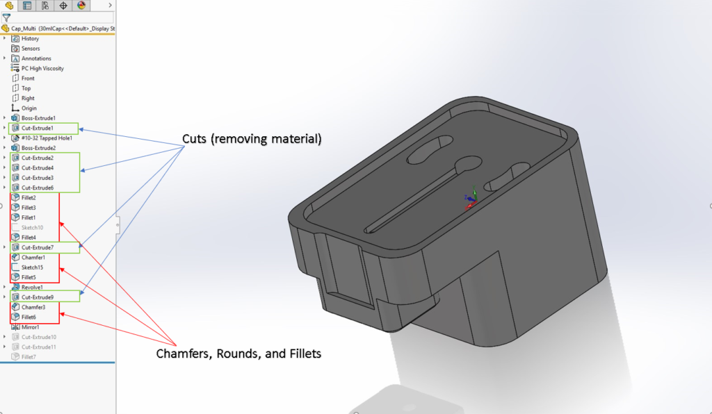
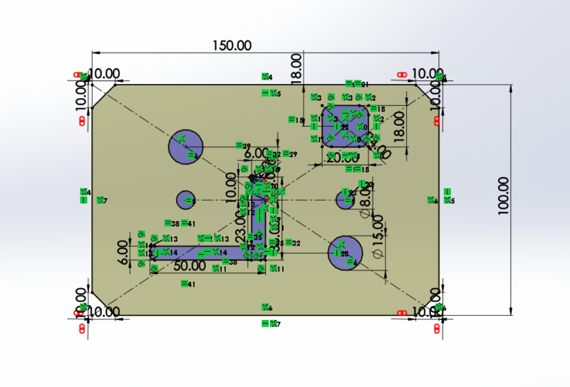
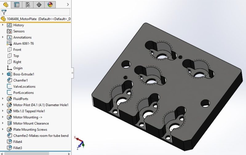
This part displays a “scattered” organization of features that is typical of the design process. A designer will typically add features when they are needed without consideration of the feature tree order and organization. Good design practice would be to either insert the features directly into their preferred location in the tree or go back and re-order the features when convenient.
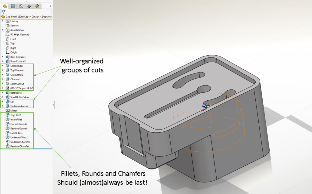
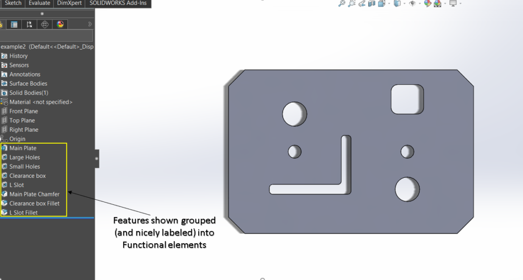
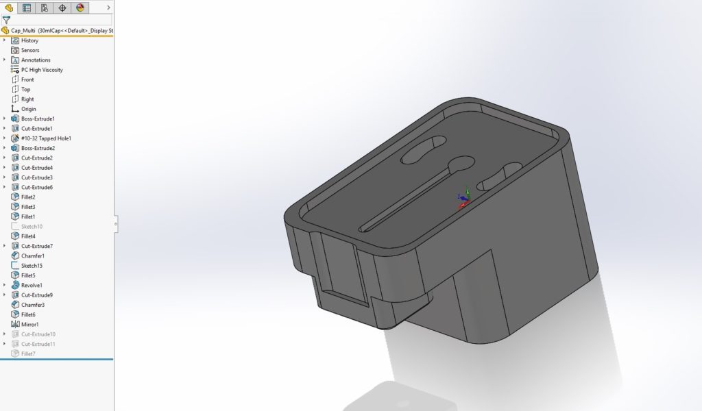
This is the same part with a well-organized, easy-to-understand feature tree.
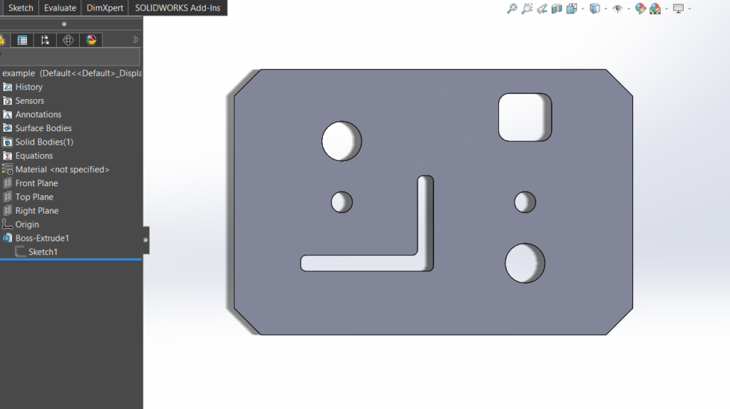
For simple, largely two-dimensional parts such as these, it is tempting to “get it done” by simply extruding a single sketch. Better design practice is to separate features into their functional elements as shown below. A new engineer tasked with changing this part will have a much easier time understanding what to do—and is less likely to make unintended changes.
#3: Keep your sketches simple!
This is an easy one, but it has changed since the early days of CAD. If you are creating a simple machined part with rounded corners and a few holes in it, it is often tempting to model it as a single feature. In the early days of CAD, computer processing time and memory resources could be spared by grouping as many features as possible into a single sketch. Thankfully, those days are over! Keep your sketches simple and add your holes and rounds as separate features. Finding a particular feature in the feature tree is much easier than finding a single feature buried in a complicated sketch.
#4: Fully define your sketches!
Most engineers already preach this one and still it is frequently broken. Indeed, when designing new parts, we don’t always know what the dimensions could be or should be. We often just know we want something roughly where we see fit. However, once the design becomes clearer, it is important to go back to the under-defined sketches and properly define them! Each CAD system helps by identifying underdefined sketches—SolidWorks, for example, shows these elements in blue, while fully defined elements turn black. If your sketch elements were created over an existing assembly, be careful not to allow SolidWorks to automatically create a reference to the assembly! If it does, delete the reference and define it only in the context of the part. This is covered in an upcoming rule, but worth mentioning again. We should also make every effort in the process to follow the next rule.
#5: Dimension your features as you want them dimensioned on the 2D Drawing.
If you know that your 2D drawing of the part will dimension a feature from an edge or other feature, dimension the defining sketch that same way! This is more of a guideline and a “nice-to-have.” Doing so dramatically simplifies the 2D drawings and makes future editing a snap—often right from the drawing itself! It does involve rigor not commonly used, however. This rigor includes frequently returning to the part model while creating the drawing, editing sketches such that the dimensions in the part show up as desired on the drawing. When done properly, no dimensions need to be created on the drawing. Instead they can be shown as “model items”. In SolidWorks and in Creo Parametric, only dimensions shown in this manner are fully bi-directionally associative in the drawing. They are also less likely to lose one of their attachment points when the part is altered. My personal recommendation is to use your best judgement and intuition when you create the part. The more you practice this rule, the better you will get over time.
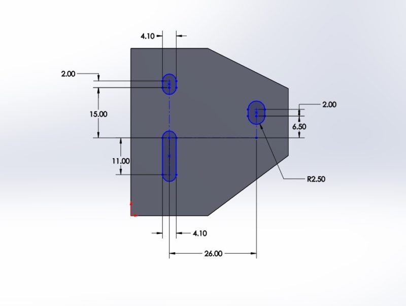
This sketch is underdefined. SolidWorks shows underdefined sketch elements as blue. In this part’s case, the important parameters are the slots’ relationship to each other, not necessarily to the overall part. Still, good practice dictates that the slots be tied down.
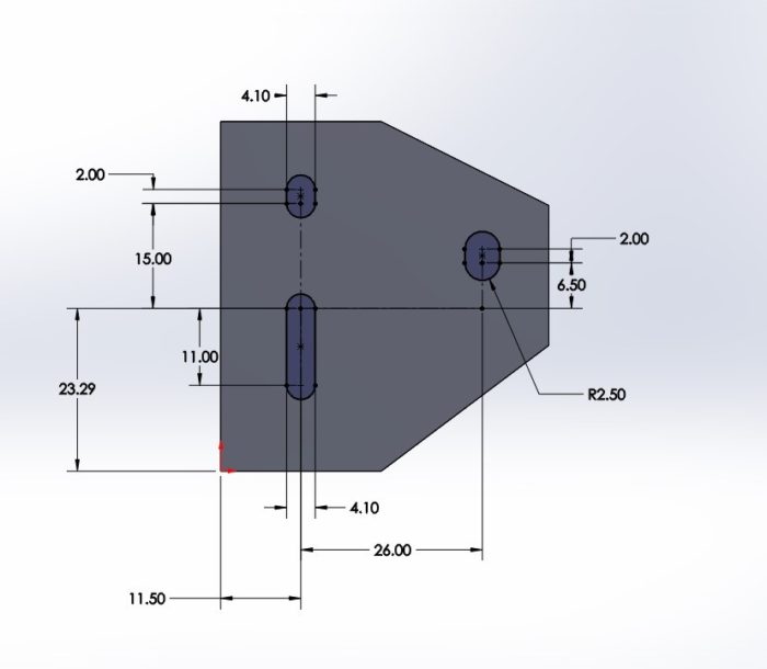
This sketch ties them down to the lower left corner of the part. This can prevent the slot-pattern from moving unpredictably if the exterior dimensions of the part change.
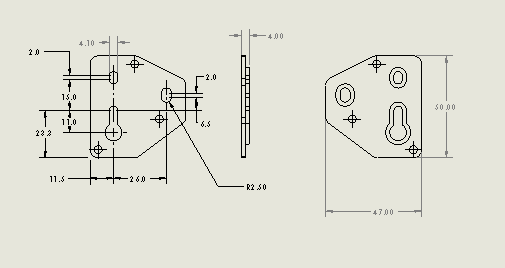
If we wished the slots in the prior example to be shown on the drawing all dimensioned from the part’s edges instead of how shown above, we could go back to the sketch and redefine it that way. While this is less commonly practiced and can remove some design intent, it does make future revisions much easier and is considered good design practice.
#6: Remove all external references!
One of the most powerful capabilities of modern CAD systems is the ability to create parts within the context of a larger assembly. This ensures that mating features of each part such as screw holes, tabs, edges and surfaces all align properly in their assembly. Modern CAD systems will even enable these features to stay referenced to their mating parts, such that a change in one part will automatically change the other. While this sounds like a great convenience, it is generally considered terrible and dangerous engineering practice. It is acceptable and often very helpful to use external references to define these features. Once defined, however, one should always go back to the part and remove these references and fully define them only within the context of the part. Best practices would be to set your CAD system to not allow external references.
The motor mounting holes shown above were placed in context with the attached motor to ensure that they line up with the mating part.
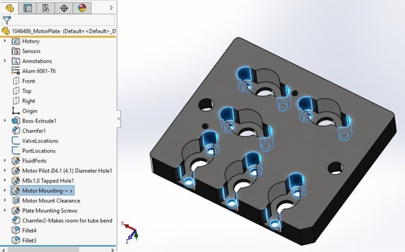
The “->” after the feature in the tree denote that this is an external reference. Break these references and completely define the feature within the scope of the part.
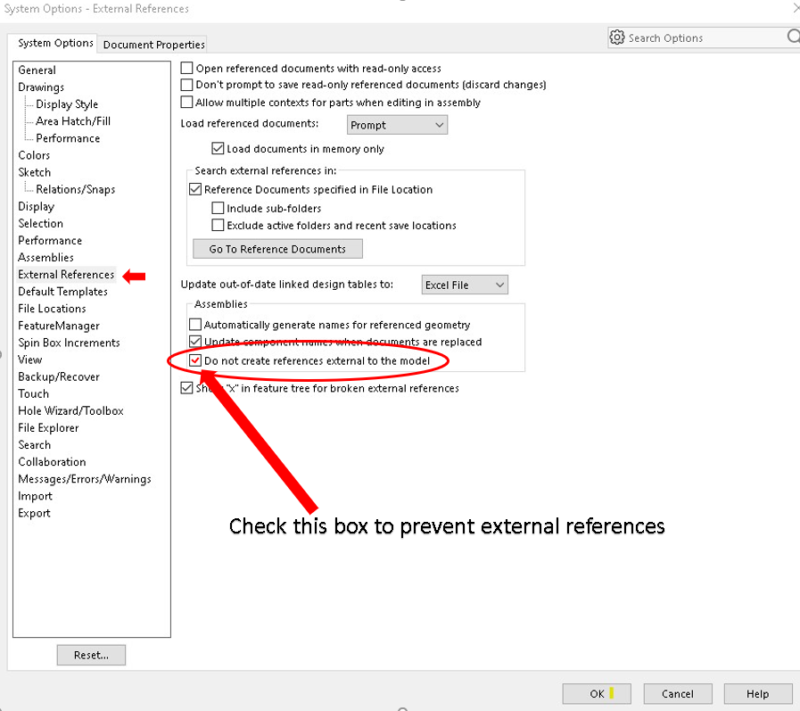
Best practice would be to turn off the ability to use external references in the CAD Settings.
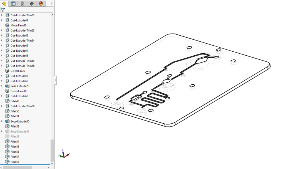
Shown here is a real part with 166 features in the feature tree. Note the size of the scroll bar! About halfway up the tree, Cut-Extrude32 is a large, rectangular cutout that effectively erases all the features that came before it. The design process is a creative process that may involve many twists and turns. Somewhere in the process, however, there must be a transition to reality. Part of that transition must include “cleaning up.”
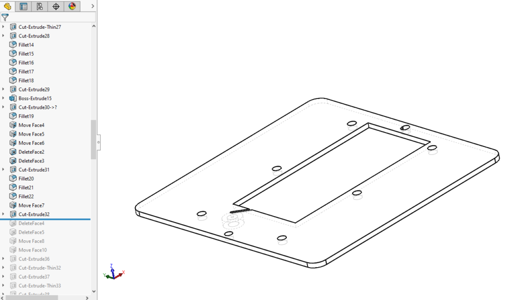
The result of this design process should have been a relatively simple part that could be modeled with about a dozen features. There are many other examples visible about how this part breaks many of the rules—and that is FINE during the design. Just remember to clean up before you finish! The result of not following established engineering practices in this part resulted in much longer times to make simple revisions.
#7: Remove orphaned features.
Often in the design process, a part evolves through the addition of features over time. Frequently you will add a hole, a cut, or a protrusion that completely engulfs one or more features. To maintain a well-organized model, you should delete a feature that is rendered obsolete by a later feature. Additionally, if you find you need to add just a bit more length or material to a part, it is best to alter the original feature that created it, rather than extending it with another feature.
#8: Fillets, rounds, and chamfers should be the last features.
Fillets, rounds, and chamfers should always appear at the bottom of the feature tree. It is acceptable to create parts to be injection molded with fillets near the top of the feature tree, immediately prior to a SHELL feature. Fillets, rounds, and chamfers should never be used when locating other features—keeping them last ensures that you do not.
Examples from #2, #6 and #7 all show the correct and incorrect places to add these features. Please keep these last unless there is a very good reason not to!
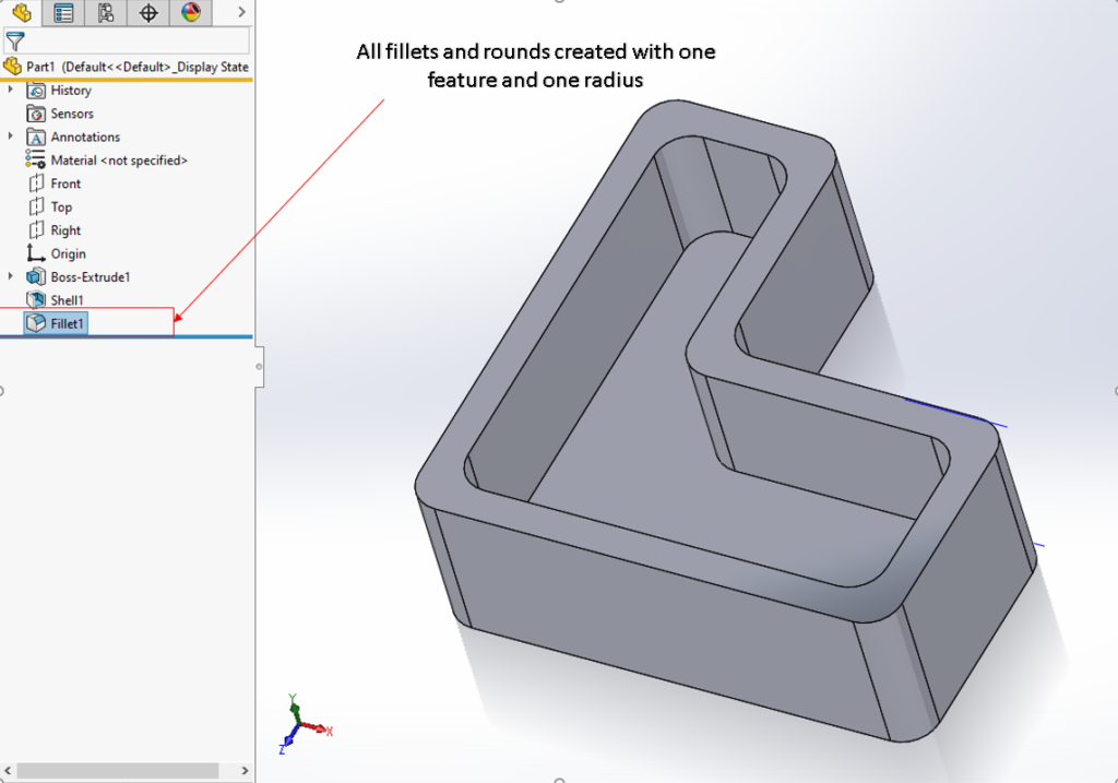
This part shows all fillets and rounds created with a single feature. If it is desired to increase the internal fillets, but leave the outer radii as it is, it is much easier if these are separate.
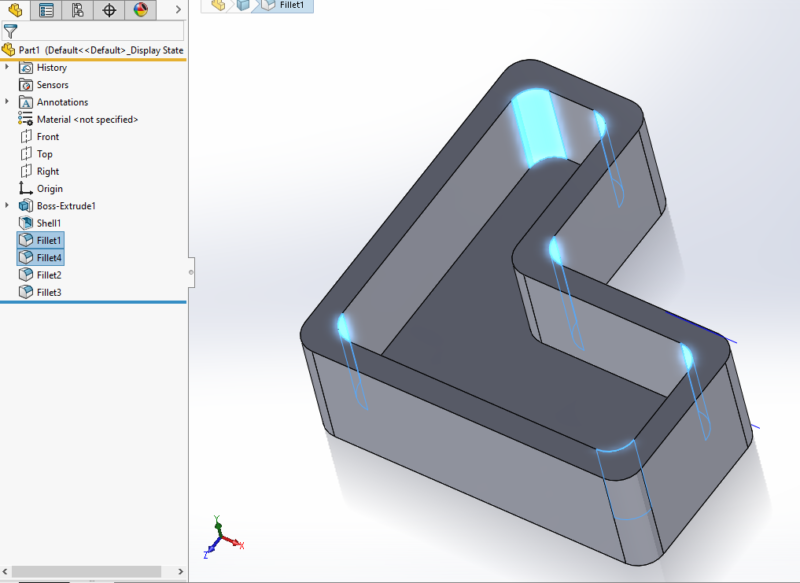
This part is identical, but each group of fillets and rounds can be modified separately.
#9: Fillets are not the same thing as rounds!
Keep fillets and rounds as separate features. It is all too convenient to start a FILLET feature and just start clicking edges. However, internal corners (fillets) have different requirements than external corners (rounds). The DFM process frequently demands altering the radii for each separately. Keeping internal fillets as separate features from external rounds ensures that they can be separately specified.
#10: Bonus Points: Name your features!
All these secrets are intended to help the designer create a robust design that can be easily understood and edited over the entire lifetime of the product. One final way to ensure that your design is more easily understood and edited is by re-naming your features to something more meaningful than “Cut-Extrude237” or “Boss-Extrude43.” “AmplificationChamber” or “HolesForHinge” are much easier to find and understand in the often-huge feature tree.
To summarize, product design is a journey that involves many decisions and compromises. In all engineering disciplines, these decisions and compromises will greatly affect the product for its entire lifecycle. Design technique and model quality are rarely considered in the mechanical design world, but they are just as important to the product as that first functional prototype. The best method for learning proper modeling technique and quality is through mentoring and experience. Hopefully, these 10 secrets have provided you with a useful framework to create robust models that are simple to understand and edit, even by other engineers.
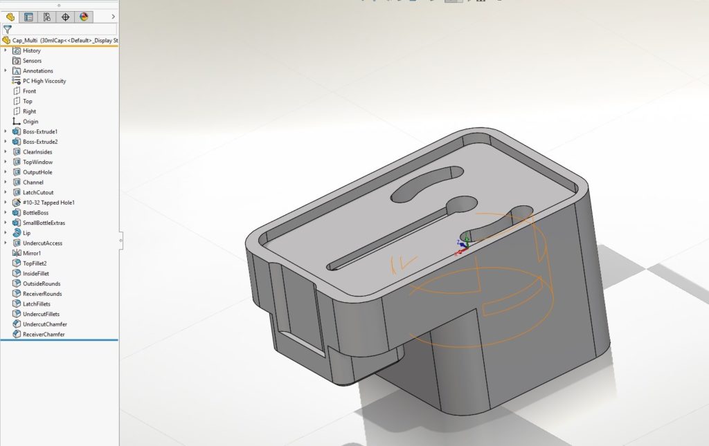
The example part from Rule 2 is also a great example for feature naming. Isn’t it much easier to identify a feature in the tree if it tells you what it is? If one needed to widen the “channel” or enlarge the output hole, having features named properly can save time and money!
This part shows all fillets and rounds created with a single feature. If it is desired to increase the internal fillets, but leave the outer radii as it is, it is much easier if these are separate.
If you need help designing a new product, please contact us so we can discuss your options!