Pulse Width Modulation (PWM) sits at the heart of many motor control implementations, from simple DC speed control to the precise step timing required by modern stepper drivers. While generating a basic PWM waveform is straightforward, producing high rate, jitter free, dynamically changing pulse trains can push a microcontroller’s real time capabilities to their limits. Stepper control, where every pulse represents physical motion, demands both accuracy and determinism: pulse widths must meet driver specifications, timing between pulses must be exact, and acceleration profiles must be followed without interruption.
The conventional way to generate PWM pulses is through a periodic interrupt toggling a GPIO (General Purpose Input/Output) or updating a timer compare register. This approach works at lower speeds, but as pulse rates increase, interrupt overhead can easily become a bottleneck. Context switching begins to consume significant CPU (Central Processing Unit) time, priority inversions introduce jitter, and competing ISR (Interrupt Service Routine) activity can cause missed steps and unstable motor behavior.
A far more robust solution is to offload pulse generation to the microcontroller’s Direct Memory Access (DMA) engine. By streaming precomputed timing values directly into a timer’s compare register, DMA can drive the PWM hardware autonomously: no CPU intervention, no latency, and essentially no jitter. This frees the processor to run motion planning, communications, or safety tasks while the hardware generates a perfectly timed pulse train.
This blog introduces how DMA-driven PWM works, why it is ideal for motor-control applications such as stepper drivers, and how to structure your firmware and hardware to take full advantage of this technique.
PWM and Stepper Motor Fundamentals
A stepper motor moves in discrete angular increments by energizing coil phases in sequence. In full‑step mode, each change in the motor’s drive phase (each electrical step) rotates the shaft by the motor’s native mechanical step angle, which is typically 1.8°. Half-stepping and micro-stepping subdivide each full step by partially energizing two phases simultaneously, trading peak torque for smoother motion and smaller step resolution.
Many modern stepper motor drivers (e.g. TMC2209, DRV8825) accept a simple two-signal interface: a STEP line whose rising edge advances the motor by one step or micro-step, and a DIR line to set direction. The microcontroller generates a square wave on the STEP line at the desired pulse rate, and the frequency of the pulses maps directly to motor velocity.
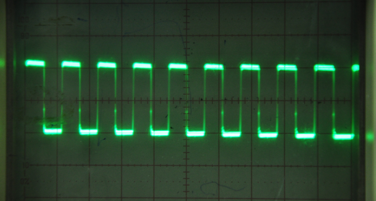
The timing requirements are straightforward but strict. A minimum pulse width (typically 1–2 µs) must be maintained on the STEP line and the inter-step period determines speed. Critically, the motor cannot instantly jump to full speed; the PWM signal must be ramped up and down because the rotor’s inertia limits how quickly it can follow the rotating magnetic field and exceeding that limit causes missed steps or a stall. Missed steps result in a loss of positional accuracy with no inherent feedback to correct the error, while a stall can cause the motor to stop completely, producing vibration, noise, and potentially requiring a re‑homing or reset to recover accurate position.
The DMA Advantage
Direct Memory Access (DMA) is a hardware engine inside the microcontroller able to transfer data between memory and peripherals independently of the CPU. You configure a source address, a destination address, a transfer count, and a trigger. The DMA controller then runs independently, firing off transfers each time the peripheral signals ready.
For PWM generation, the destination is the timer’s capture/compare register (CCR). Every time the timer overflows, it triggers a DMA request. The DMA writes the next value from a RAM (Random Access Memory) buffer into the CCR, changing the timer period for the next cycle. The result is a hardware-timed, CPU-free pulse train, whose timing is as deterministic as the oscillator driving the timer. See Figure 1.
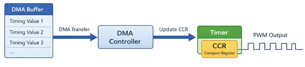
Figure 1: DMA-Driven Data Flow
Compare this with a CPU-driven approach: an interrupt fires on each timer overflow, the CPU saves context, executes the ISR, restores context, and returns. At higher step rates, the ISR servicing overhead becomes significant and competes with every other interrupt source in the system. Any priority inversion adds jitter directly to the pulse train output. See figure 2.
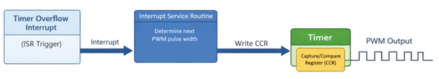
Figure 2: ISR-Driven Data Flow
DMA-based PWM is particularly valuable when ISR servicing begins to overwhelm the CPU, when the system runs an RTOS (Real-Time Operating System) with non-deterministic interrupt latency, or when multiple axes must operate simultaneously without one starving the others of processing time.
Once you decide to move pulse generation into hardware, what capabilities do the timer and DMA peripherals need to support this approach?
What the Hardware Actually Needs to Do
At this point, the idea is straightforward: let the DMA controller feed timing values into a timer and let the hardware generate the pulse train. For that to work, though, the timer and DMA peripherals need to support a few capabilities.
First, you need a hardware timer capable of generating PWM output. This output becomes the STEP signal sent to the motor driver. Each timer period produces one rising edge on the STEP output to advance the motor by one step or micro-step. The interval between rising edges determines the motor’s speed.
Next, the timer must be able to trigger DMA transfers from timer events, typically an update event when the timer counter rolls over, or a compare event. Each time the event fires, DMA copies the next value from a buffer in memory into the timer’s capture/compare register (CCR).
This is where the flexibility of the buffer comes in. Instead of using a single constant period, the firmware can preload a table of pulse timing values representing an acceleration ramp, a constant-speed region, and a deceleration ramp. As the timer runs, DMA streams those values into the timer one by one, turning that table into a hardware-driven motion profile.
In practice, you only need three capabilities:
- A timer with PWM output
- DMA requests triggered by timer events
- The ability to update timer registers via DMA
Most modern microcontrollers provide these features, so implementing this approach is usually more about organizing firmware than finding the right hardware.
Features You Might See (But Probably Don’t Need)
When you start exploring timer peripherals in more detail, you may notice they offer far more features than this technique requires.
Advanced timers often include capabilities such as:
- Complementary outputs
- Burst DMA modes
- Multiple DMA trigger sources
- Dead-time insertion and fault inputs
These features are primarily intended for power electronics applications, such as driving half-bridges or full-bridges in BLDC (Brushless Direct Current) motors or switching converters.
For a typical stepper driver using a STEP/DIR interface, the implementation may be simpler. In most cases, the entire system boils down to three signals and one data stream:
- A PWM output that generates STEP pulses
- DMA updating the timer registers to control pulse timing
- A GPIO line controlling direction
This minimal setup is enough to produce precise, jitter-free step timing.
Advanced timer features can still be useful in specialized designs. For example, if the microcontroller is directly driving motor phases rather than using a dedicated stepper driver. But for most motion-control applications, they’re optional. The core technique of DMA feeding timing values into a timer is simple, portable, and widely supported across microcontroller platforms.
Other Considerations
Acceleration and Velocity Profiles
Real-world moves require more than a simple fixed-speed pulse train. You will need to pre-compute step-delay tables that implement trapezoidal or S-curve velocity profiles to limit jerk (changes in acceleration) and prevent stalling. For dynamic systems where target velocity can change mid-move, the DMA buffer must be updated on the fly. This requires careful synchronization between the motion planner and the DMA half-transfer callbacks to avoid tearing the active buffer.
Multi-Axis Considerations
Scaling this approach to multiple motors is conceptually straightforward, dedicating one timer channel and one DMA stream per axis, but resource contention becomes a concern. Most microcontrollers have a limited number of DMA streams, and arbitration between simultaneous requests can introduce small timing differences between axes. For coordinated multi-axis motion (e.g. linear interpolation on a CNC gantry) you should also consider how to synchronize the timers to a shared timebase or use a higher-level coordination layer that accounts for per-axis DMA latency.
Conclusion: DMA‑Driven PWM for High‑Accuracy Stepper Motor Control
DMA-driven PWM is a technique requiring more up-front development but pays off in runtime efficiency. Once the timer and DMA are configured, the CPU is completely out of the step-generation loop. Jitter drops to near-zero, CPU utilization falls dramatically, and the firmware gains the headroom it needs for higher-level control tasks.
The pattern “pre-compute a period table, fire a DMA transfer, refill in the background” generalizes cleanly to any profile shape and any number of axes, limited only by the available DMA streams and RAM. For any system running stepper motors at non-trivial speeds or alongside an RTOS, a DMA-driven approach is much more reliable than simple ISR-driven solutions.
References
AN2820 Driving bipolar stepper motors using a medium-density STM32F103xx microcontroller