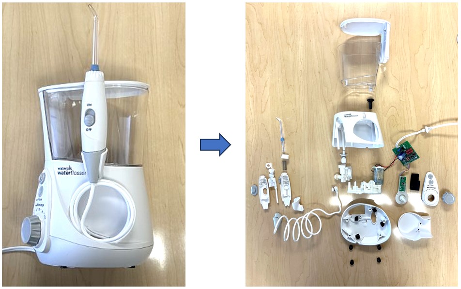
Packed with simplified design, the Waterpik Aquarius water flosser brings consumers a new approach to traditional flossing. Gone are the days of broken minty strings that often snap into your gums when that stubborn piece of popcorn won’t budge! Waterpik leverages pressurized water to safely and effectively remove debris not only between your teeth, but also from under your gumline. Not only is water flossing easier, but it also requires less time and saves money at the dentist! Just add water and you’re ready to go.
While we certainly care about clean teeth, we’re engineers, so the goal of this teardown is to better understand the various subsystems that make up the product and give you insight into how it was designed and put together. This helps give ideas to other engineers, designers, and technology enthusiasts about how consumer electronic products are engineered. You may also be inspired to apply some of the clever mechanisms to your own designs!
Waterpik Aquarius Teardown
High Level
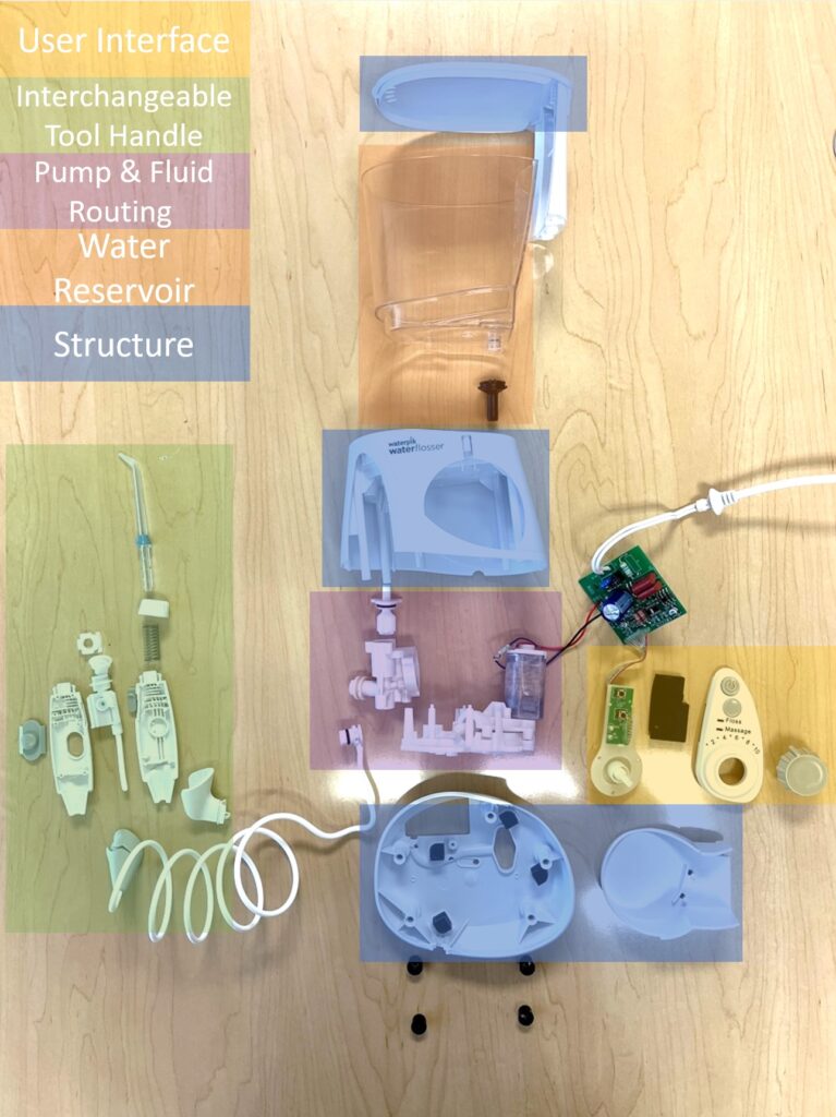
The Waterpik Aquarius has 5 main systems:
- User Interface
- Interchangeable Tool Handle
- Pump & Fluid Routing
- Water reservoir
- Structure
In this blog, we perform a teardown of the Waterpik Aquarius water flosser to reveal the hidden features such as: intriguing mechanisms (reciprocating motion, leaf springs, relief valves, etc.), how the tool pressurizes the water at various pressures, how the tool was made (injection molding and assembly techniques), and many more features that make interacting with the Waterpik simple and adjustable to your preferences!
User Interface
Using the water flosser is very simple due to its combination of digital and mechanical inputs. Simply press a button to turn it on and press another to choose between 2 modes. Then, choose how much pressure you want coming out of the nozzle by turning the power dial. Take a look below to see how these inputs allow you to tune your water flosser.
Digital
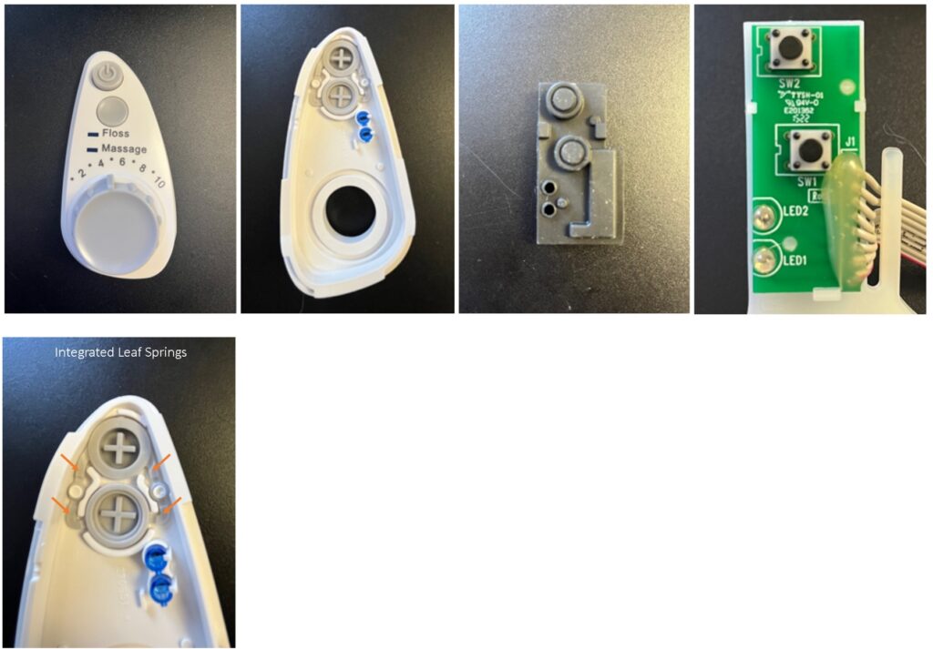
The exterior buttons are held to the structure with integrated leaf spring features, which allow them to be pressed inwards and then return to their original position. This clever design avoids additional parts during assembly by leveraging the modulus of elasticity (springiness) of the material used. Behind those buttons, a rubber over-mold covers 2 tactile switches for a soft press. These switches send a signal to the main board indicating you have interacted with the tool and switches its current state. For “Power” this feature toggles On and Off and for “Mode” it toggles Floss or Massage. The tool shows you its current state on the front panel via 2 blue covers over LED lights.
Mechanical
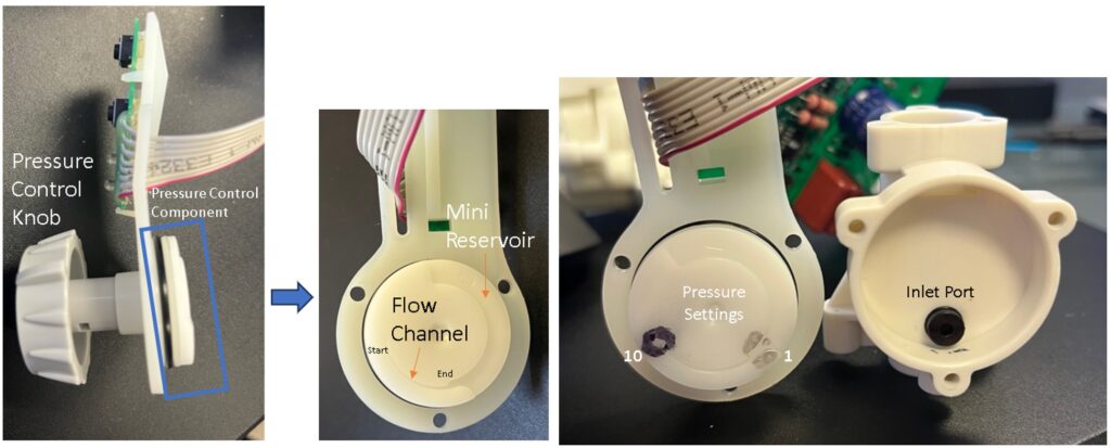
Waterpik opted to use a purely mechanical approach to control how much pressure you experience while flossing. This is done through the dial indicator on the front, which acts as a varying flow restrictor from levels 1-10. We will get into the fluid path under “Pump & Fluid Routing”, but for now, know that the position of the knob controls the water’s path, as well as how much resistance that flow path provides.
If the dial is at a 10 (black mark in the image above), the fluid can only pump through the hose and out of the nozzle because the inlet port gasket is mostly sealed on the flat face during the pump’s extension stroke. As we move the dial towards 1, we introduce an alternative flow channel and shorten its distance to a larger volume area (mini reservoir). Now, some of the water goes to the nozzle and some back into the tool for a single pump stroke. By shortening the channel, the secondary path to the mini reservoir becomes easier and easier to reach until setting 1 (silver mark in image above), where the inlet port sits just before the mini reservoir. Note that the settings appear reversed in the image since the component is flipped around.
Interchangeable Tool Handle
Tool Capture
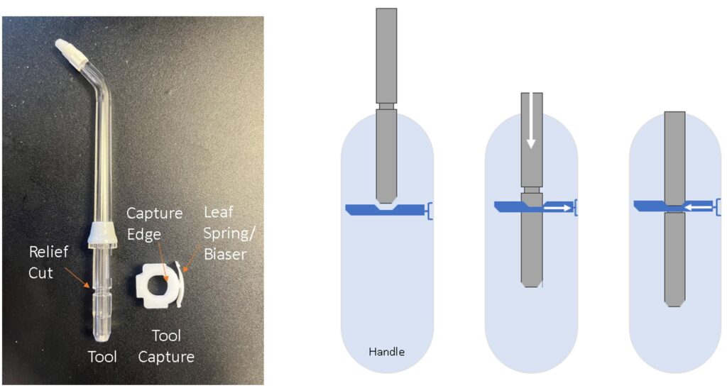
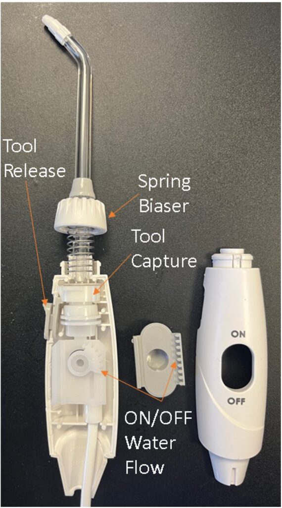
Each tool has a relief circling the diameter to trap the tool capture edge. The tool capture has a leaf spring built into the design that constantly biases it away from the handle wall. In this position, the edge overlaps the tool relief; something must force the tool capture back towards the handle walls to allow tool removal. The capture edge is slanted downwards so when the tool is pressed in, some of the downward force is translated to horizontal force and the leaf springs are compressed. The tool continues to slide down with the capture tool displaced until the capture edge finds the smaller diameter of the tool’s relief and snaps back into place. Therefore, you don’t need to press any additional buttons to insert the tool.
Tool Release
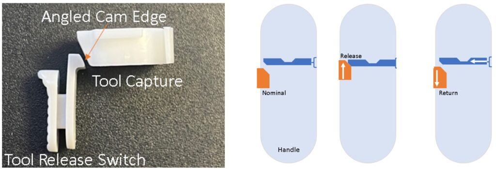
Much like the tool capture, the tool release switch utilizes an angled edge to translate vertical motion into horizontal. When pushing up on the tool release switch, the tool capture leaf springs compress, which frees the capture tool edge from the relief. At this point the tool is biased upwards and out of the handle. Since the relief is no longer exposed to the capture edge, the tool can freely slide out. Once the tool is removed and the tool release switch is released, the tool capture leaf springs’ forces push back horizontally onto the tool release switch’s edge, translating back to vertical motion and forcing the switch back down into place.
Spring Biaser
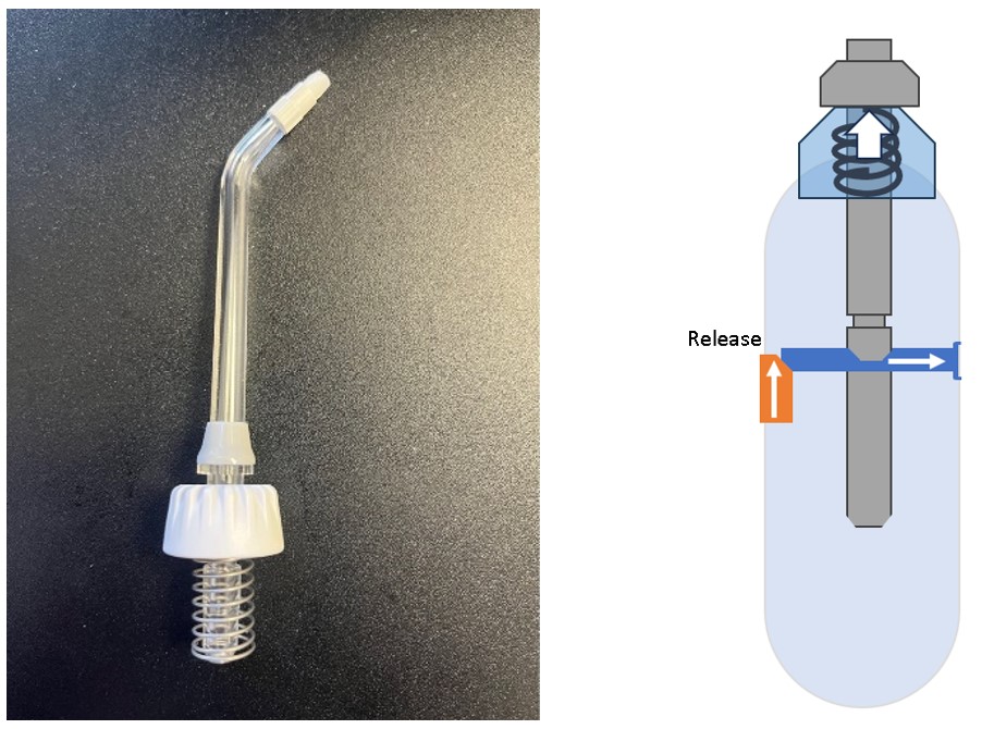
The spring biaser removes the clearance between the tool capture edge and the tool relief height by forcing the tool upwards until the edge and top of the relief make contact. This allows a very generous gap tolerance between the relief height and tool capture edge. As mentioned above, the spring also ejects the tool when the tool release is engaged so you don’t need to hold the tool release switch and pull the tool simultaneously. All these springs and angled cam edges are to ensure simple one-handed use.
ON/OFF Water Flow
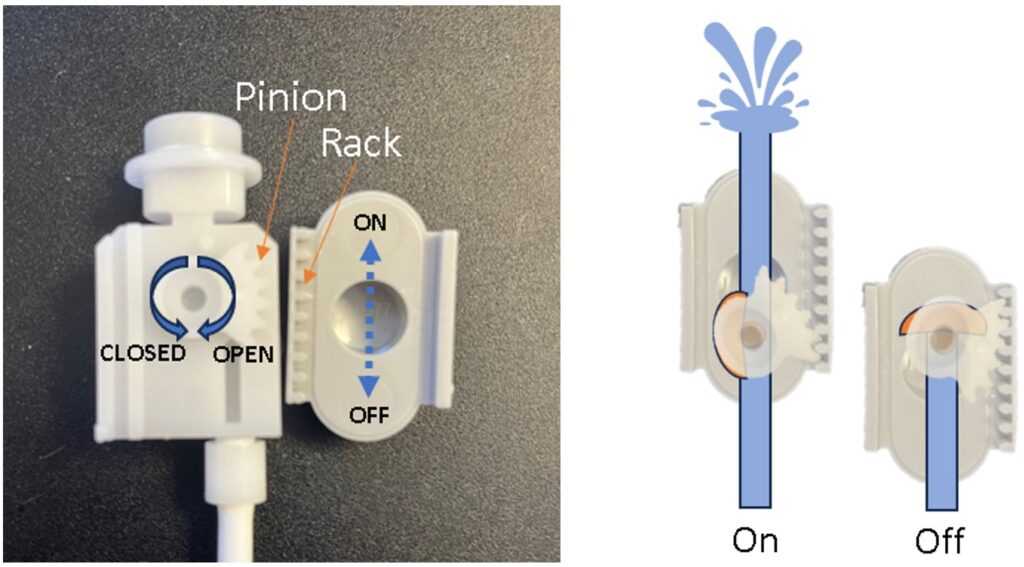
To turn water flow on and off, even when the tool is powered on, a rack and pinion gear cleverly translate linear motion of the “on/off” switch to rotational movement. The pinion gear has an internal semi-sphere valve that rotates to cover the water conduit when in the “off” position but rotates out of the way for the “on” position.
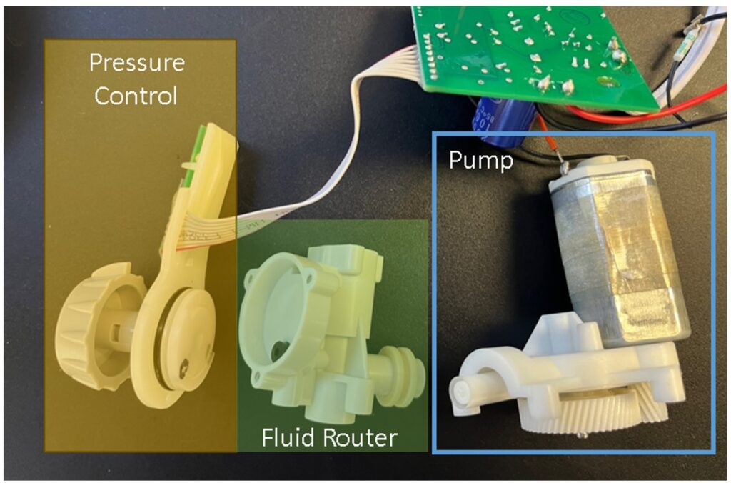
Pump & Fluid Routing
Pump
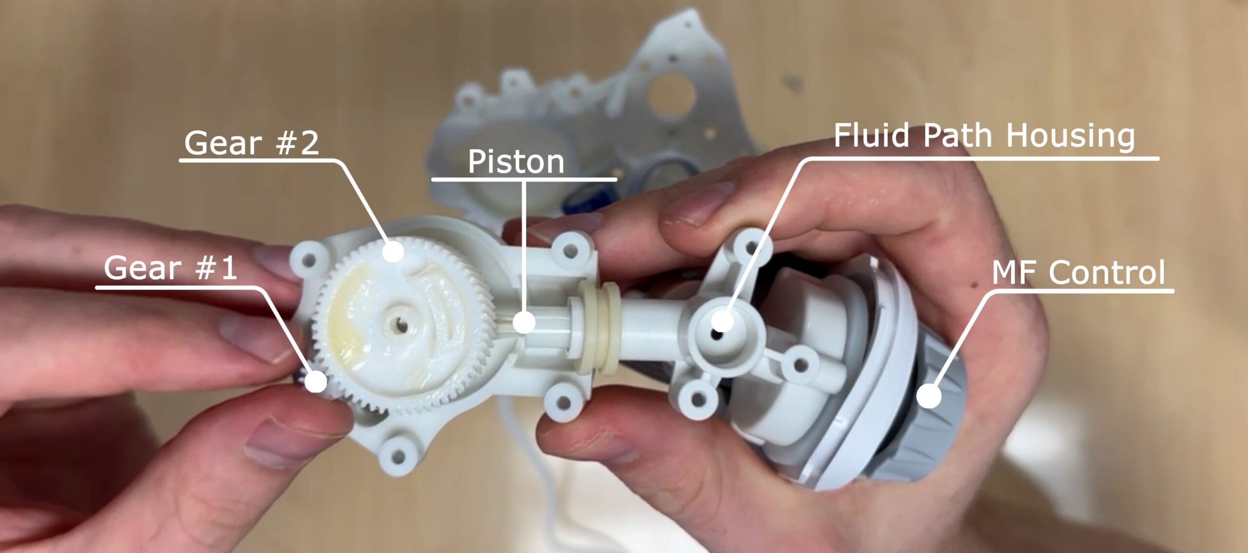
To produce pressurized water, the Waterpik incorporates a reciprocating positive pressure pump. This is a popular pump design with very few moving parts. It comprises of the following components:
- A pump to generate motion
- Gears to transmit the motion and increase torque/force
- An off-center crank cam to translate rotary motion into linear motion
- A piston to move linearly and displace the water
- A cylinder to create suction and direct the water
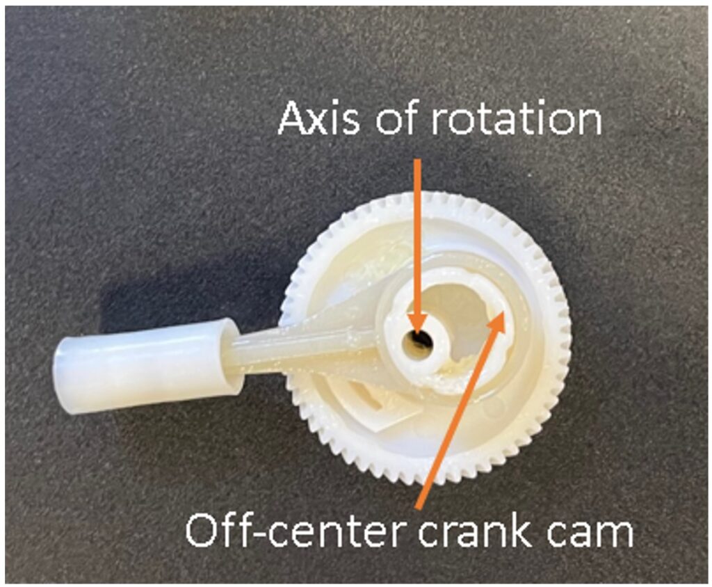
The off-center crank cam is a circle with its rotation axis on the perimeter overlapping with the helical gear center axis. As the gear rotates about its axis, the theoretical center of the off-center circle moves like a clock hand. In part of the rotation, the cam center will be to the left of the gear axis and in the other part of the rotation it will be to the right of the gear’s axis. Since the piston is translationally coupled with this motion, it will move back and forth. However, the piston rod will be prevented from rotating by the cylinder it inserts into, therefore the piston loop will spin on the surface of the outer cam edge.
Gears
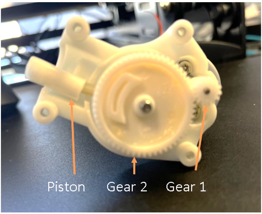
There are only 2 gears in the pump drive assembly. The first smaller gear attaches directly to the motor shaft. The second gear in the pair drives the piston. The second gear is much larger which means it has a higher torque than the gear at the motor output, at the expense of speed. Helical gears are chosen over spur gears to reduce noise, vibration, and increase the durability and lifespan of the pair.
Routing
Now that we’ve discussed the reciprocating pump, let’s break the fluid routing into 2 actions: pump retraction and pump extension.
Pump Retraction
As the piston retracts, a vacuum is created in the lower portion of the fluid router that suctions water from the reservoir to the top of the fluid router, through the pressure controller, and then back into the lower portion of the fluid router. Once pulled through the pressure controller’s outlet, the fluid is back in the router but below and separated from the initial inlet point.
Pump Extension
Once water has filled the lower portion of the fluid routed, the piston starts to extend and forces the water backwards with positive pressure. Water is incompressible, so the shrinking volume caused by the piston taking up more and more of the cylinder internal diameter forces the fluid to find an escape route. The path of least resistance is through the waterpik tubing, with some water escaping back into the pressure controller – depending on the setting – as discussed in the mechanical interface section.
Pressure Relief
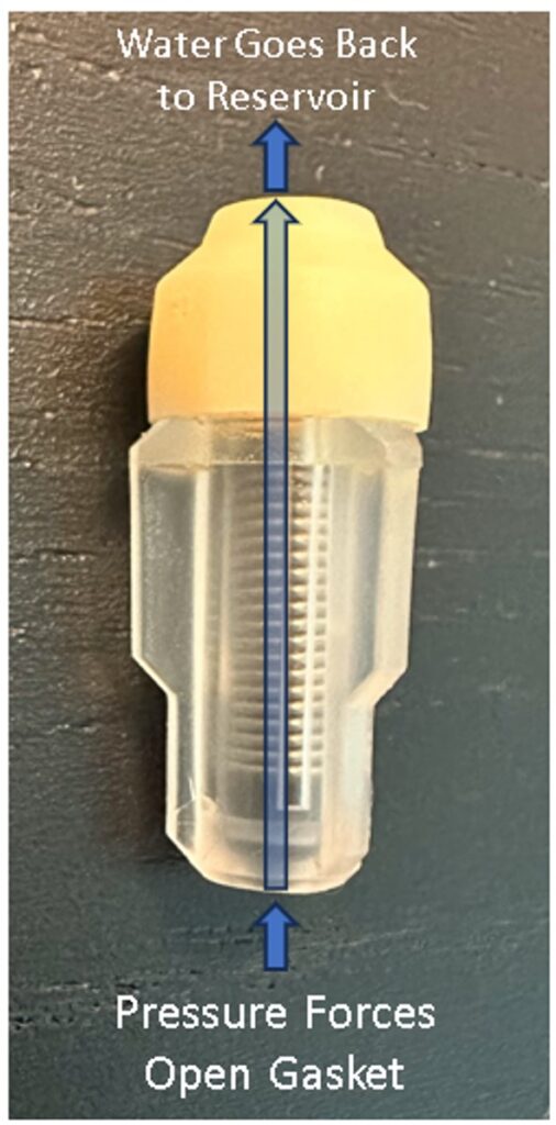
Partitioning the upper and lower portions of the fluid router is a pressure relief valve. If pressure builds too high, the valve allows water to flow back into the upper portion of the fluid router and into the reservoir. The valve is normally spring-biased closed, but with enough force the spring can compress and allow water to flow upwards through the valve center.
Water Velocity
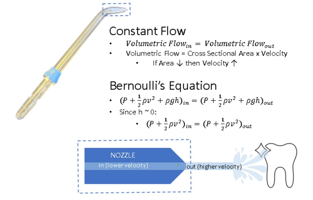
If you’ve ever used a water flosser, you’ve probably noticed the water flows out of the tip very fast. To avoid solely relying on the pump to achieve this velocity, Waterpik takes advantage of Bernoulli’s equation to increase the water’s exit speed via a tapered nozzle on the tool. In summary, this principle tells us that under certain fluid conditions (inviscid, incompressible, equivalent height, etc.), of which water meets in the Waterpik, the energy of a system is constant. Since we know that the volumetric flow rate is also constant, if we make the tool’s cross sectional inner diameter narrower at the tip then the fluid will speed up. But how can water gain the energy to increase the velocity? Nothing in a system is free. The higher static pressure behind the nozzle gives the ejecting fluid the energy required to speed up through the constriction.
Water Reservoir
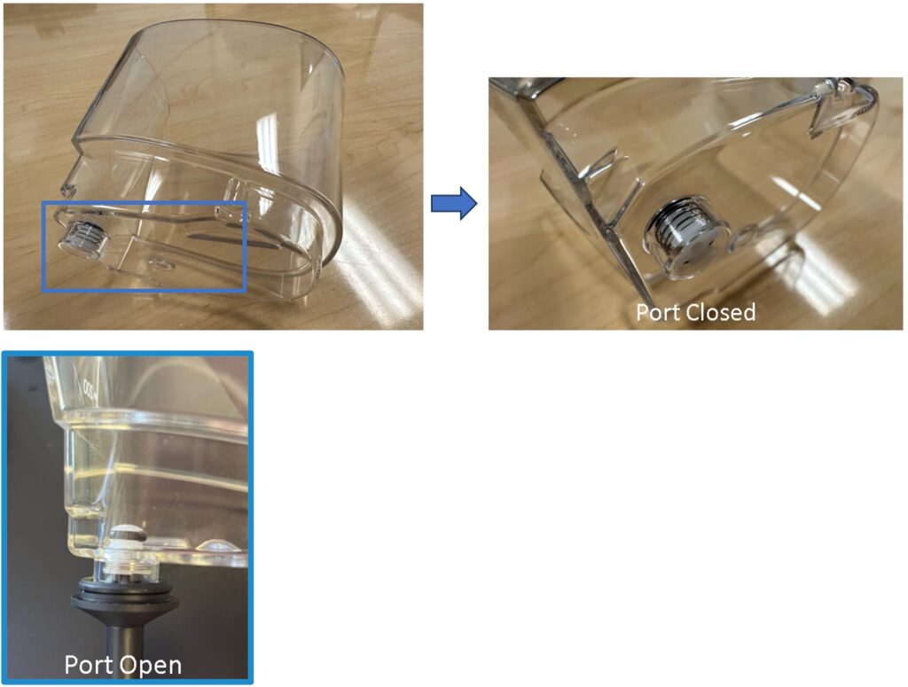
Aside from electricity, water is the Waterpik’s other obvious consumable. To remove the necessity of being connected to an external running water source, the Waterpik incorporates a reservoir for holding excess water and painless refilling. More than just an empty bucket, the Aquarius reservoir incorporates a spring-loaded port to allow dripless filling and avoid over pressurization.
By encapsulating a compression spring, the port is biased shut and the gasket on top seals the water from flowing out the bottom. This is the default state when the reservoir is separated and being filled. Once the reservoir is set back onto the Waterpik’s base, a protruding poker attached to the tool, with a hole in the center, compresses the spring and pushes the gasket up to remove the seal. This allows water to flow through the tool or back into the reservoir in the case of pressure building within the flosser.
Structure
The structure of the Waterpik Aquarius is what holds all the systems together nicely on your counter. But just because it serves a simple purpose, doesn’t mean there aren’t supplemental design features that make interacting with the water flosser a better experience. Look no further than the reservoir lid!
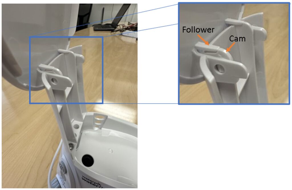
The lid is built into the structure, so you never need to keep track of loose parts when filling your water tank. However, Waterpik takes this one step further and incorporates a self-locking hinge mechanism to open it with one hand and removes the worries of it falling back down. To achieve this, the Aquarius capitalizes on a cam profile coupled with an angled leading edge cantilever beam – we will refer to this lid beam as the “follower” for simplicity.
![]()
Moving left to right in the image above, you can observe the cam surface starts after the relief and has an angled face that transitions into a large radius curve until dropping off vertically. What does this feel like to you as the user lifting the lid? At first, nothing is noticeable since the lid followers are too far from the vertical surface to contact. However, towards the top of the rotational motion, the followers contact the cam profile and gently glide along the rounded surface. Some amount of resistance is felt as the cam profile pushes up on the lid follower. Finally, at the end of its rotation, the lid finger edge engages the cam edge with a steep fall off into the relief with a tactile and satisfying click! At this point the two surfaces are parallel to each other and provide enough resistance to prevent the lid from falling back down, even if gently bumped. The angle of the edge and length of the follower are chosen with care such that the lid feels sturdy, but still requires little force to deflect the follower and re-engage with the cam so the lid can be shut.
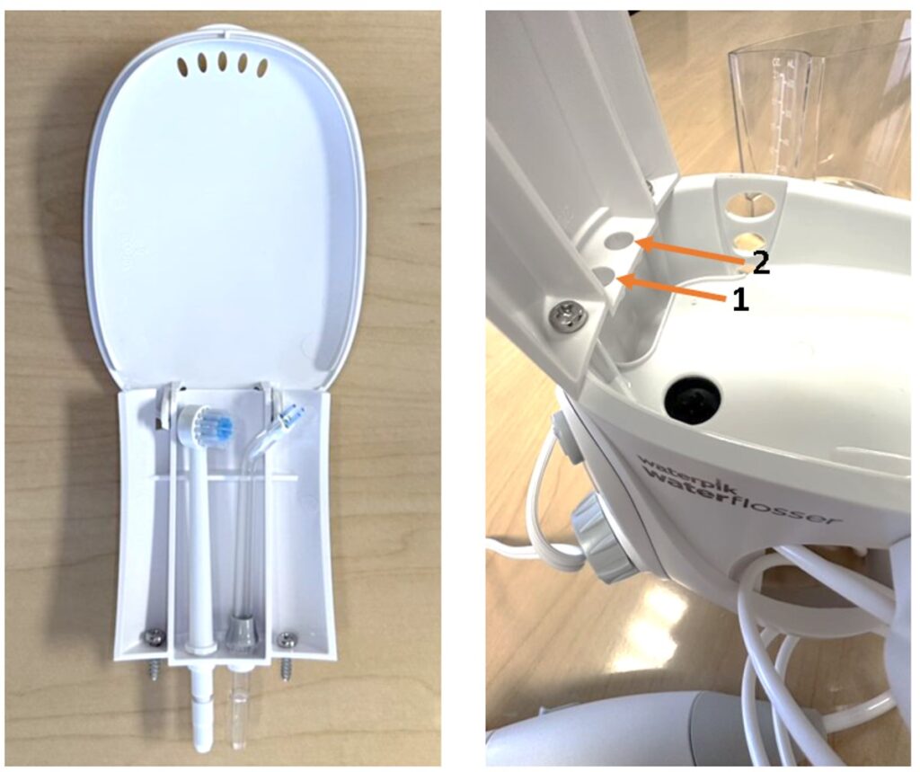
Waterpik’s lid even includes built in storage (hidden behind the water reservoir) for 2 additional tools.
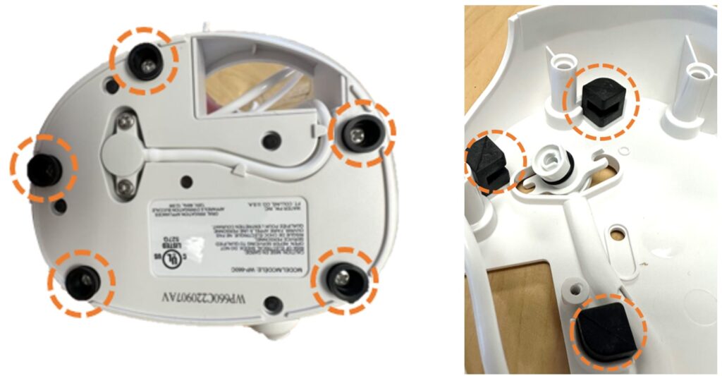
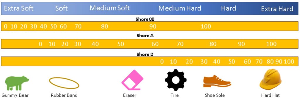
Motors rotate quickly and therefore produce high frequency vibrations, these vibrations can be loud and cause other problems such as material fatigue, solder damage, or fastener loosening. To address these issues, Waterpik leveraged existing fastener holes on the base to incorporate 5 rubber feet. The rubber prevents slipping on your bathroom counter and acts as a vibration dampener. Inside of the tool, more vibration dampening features can be found. The internal rubber grips double as an assembly aide as the whole electrical module inserts into these soft clips to flexibly hold everything in place. For low frequency vibration dampening, such as a person walking, soft rubbers are chosen. In this case, a stiffer rubber is chosen for the high frequencies and pulsing from water flosser pump system. See below for a quick reference guide to the durometers of everyday items you’re familiar with!
Waterpik Aquarius Water Flosser Teardown Conclusions
Waterpik places a lot of attention on mechanisms such as cam surfaces, leaf springs, and gears to ensure easy, single-handed operation of their waterflossing device. Rethinking how we design tools by incorporating mechanisms can turn seemingly complex motion into simple and seamless operations. We hope you enjoyed reading through this blog and took inspiration to implement user-friendly features on your next project. If you need help reducing your costs and simplifying a product, contact us to learn more about ways we can help!