Tearing down a well-designed product like the UniTree Go2 quadruped robot dog is an irresistible opportunity to learn and share exciting findings. Teardowns are more than just disassembly—they’re a way to reverse-engineer clever design choices and uncover the engineering tradeoffs that make a complex system both functional and efficient. The Go2 is a surprisingly capable quadruped robot, and what’s inside offers valuable insights into its design.
In this blog and embedded video, we dive deep into the mechanical, electrical, and design decisions that make this affordable robot so adept. You’ll learn how the designers optimized cost and complexity by reusing identical motor assemblies across all joints, implemented thoughtful serviceability features, and carefully managed shock and vibration in a high-impact environment. From custom motor control boards and planetary gear reductions to modular leg construction and robust wiring strategies, we will reveal valuable insights behind building a production-ready robotic platform.
UniTree Go2 Quadruped Robot Dog Teardown
We also offer a full Unitree Go2 Motor Teardown for those that want to dive further into the intricacies of just the motor specifics.
System Overview
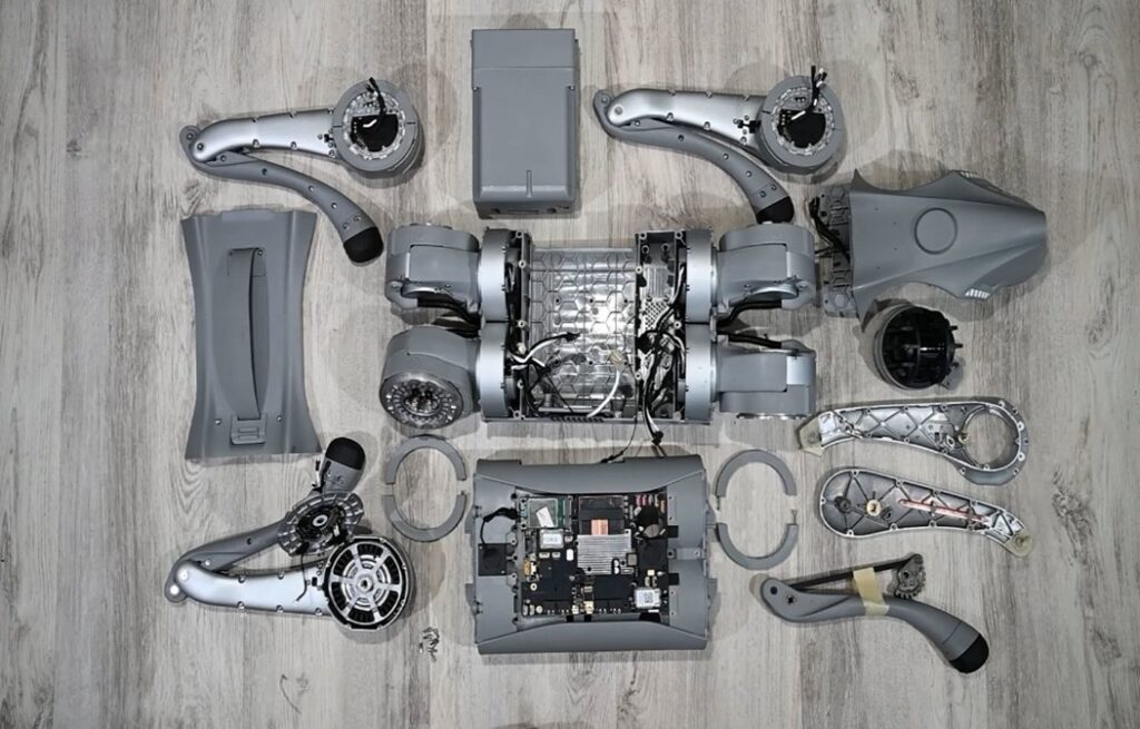 Primary Components of the UniTree Go2 Quadruped Robot Dog
Mechanical Architecture & Disassembly
The Go2 features a modular mechanical layout optimized for both manufacturability and field service. Disassembly required considerable effort, with over 60 fasteners and numerous glued or taped connections that had to be carefully removed. The design reflects a clear emphasis on robustness and long-term durability. Attention to fastener retention and meticulous cable management suggests that UniTree prioritized vibration resistance, shock absorption, and overall impact survivability, all critical for dynamic, real-world operation.
Notably, each of the four legs is a fully modular, swappable assembly with standardized mechanical and electrical interfaces, making field repairs and part replacement significantly easier and faster. This is an important advantage in both development and deployment scenarios.
Key subsystems include:
- A polymer chassis with high rib density for structural stiffness
- Twelve identical high-torque brushless DC motors
- Four modular leg assemblies with serviceable interfaces
- A robust LiDAR module and heat-managed electronics
- A high-density control board
The highest total cost of the components is likely the combined motors, although the most expensive individual component is probably the LiDAR. UniTree’s decision to use the same motor at every joint (12 in total) shows smart design for part reuse. These BLDC motors feature integrated planetary gear reduction, magnetic encoders, and onboard motor control PCBs with Field-Oriented Control (FOC) support.
The chassis, while highly ribbed and made from a strong polymer, may be slightly under designed for long-term high-impact use. However, the chosen approach reduces weight and cost while maintaining core structural integrity.
Electronics System & Thermal Considerations
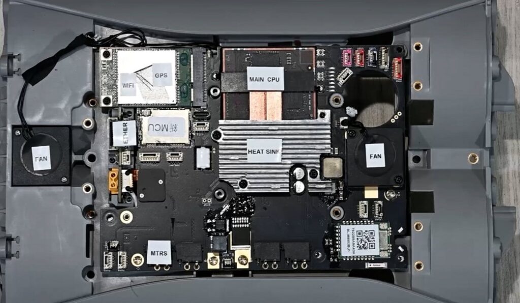 Main electronics board of the UniTree Go2 Quadruped Robot Dog
The main electronics board is well thought-out from a thermal and mechanical standpoint:
- Two axial fans guide airflow across a centrally placed heat sink
- The CPU is thermally coupled to the heat sink with optimized contact paths
- Antenna modules (Wi-Fi, GNSS) are positioned for clear signal propagation
Multiple unused connector pads suggest that UniTree designed the PCB with future upgrades in mind. Radio Frequency (RF) modules, power inputs, and expansion headers point to a scalable architecture for add-ons or future variants.
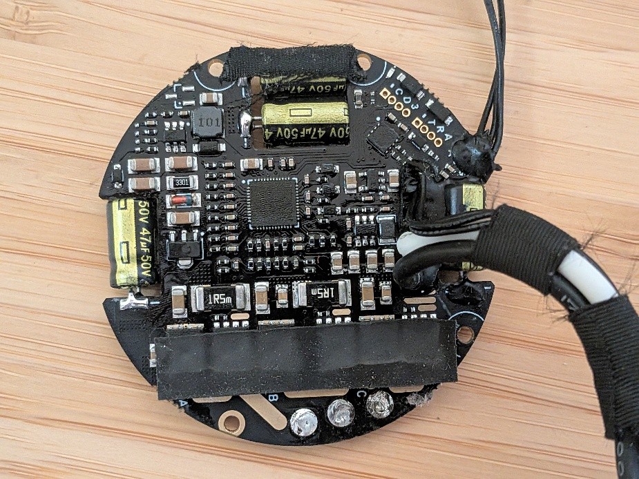
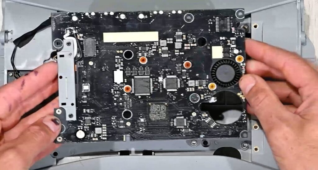 Back side of the main electronics board
Active Thermal Management:
Two axial fans are positioned to direct airflow across a centrally mounted aluminum heat sink. The CPU, likely a high-performance ARM-based SoC, is thermally coupled to this heat sink using a precise interface with thermal pads or paste to ensure low thermal resistance. Mounting pressure is likely applied via spring-loaded fasteners or direct mechanical preload to maintain consistent contact under vibration.
Signal Integrity & Radio Frequency (RF) Considerations:
Antenna modules for Wi-Fi and GNSS are strategically placed near the periphery of the board to reduce interference and maximize signal clarity through the non-metallic chassis. The PCB layout demonstrates good separation between analog, digital, and RF domains, and likely includes impedance-controlled differential traces for high-speed data paths.
Connector Retention & Vibration Mitigation:
Every electrical connector is secured with adhesive, and cables are bundled with tape or constrained using anchors. This strategy reduces the risk of disconnection under shock or sustained vibration and is especially important for components tied to motor control, encoder feedback, and power distribution. While labor-intensive, this approach improves field reliability for a system experiencing continuous dynamic motion.
Scalability & Expansion-Ready Design:
Several unpopulated connector pads and test points on the PCB suggest that UniTree has designed the board with upgrade paths and optional features in mind. These may include:
- Additional RF modules or communication interfaces
- Redundant or auxiliary power connectors
- SPI, UART, or I2C headers for peripheral expansion
- Provisions for onboard storage or debugging interfaces
Together, these details reveal a tightly integrated electronics system that balances high performance with ruggedness and adaptability. The design reflects an understanding of real-world operating conditions while leaving room for product evolution, custom applications, or future sensor integration.
LiDAR (Light Detection and Ranging) Integration
 LiDAR Module Disassembled
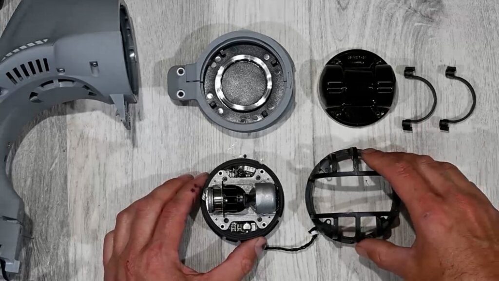
The Go2’s head-mounted LiDAR is a compact, rugged sensor that plays a key role in navigation and perception. It uses a dual axis spinning mechanism to emit laser pulses in all directions, measuring the time it takes for the light to bounce back from nearby objects. As the unit rotates, it collects vertical and horizontal slices of the environment, which are stitched together into a complete 3D view. This time-of-flight data, combined with the scanner’s rotation angles, allows the system to calculate the 3D position of surrounding surfaces. The result is a full 360-degree point cloud that updates continuously, enabling the robot to map its environment, avoid obstacles, and localize itself in real time.
Real-time mapping from Unitree Go2
Mechanical Housing and Protection:
The LiDAR unit is encased in a precision-machined aluminum cage that has been welded and anodized. This construction provides a rigid enclosure with high corrosion resistance and excellent structural stability. The cage protects delicate optical and electromechanical components from impacts and debris, which is critical in mobile robotics applications operating in unpredictable environments.
Mounting Interface and Alignment Strategy:
The LiDAR is mounted to the robot’s chassis using a split collar design that provides concentric alignment and firm seating. A spring washer is incorporated into the mounting stack to apply a controlled preload, ensuring consistent axial force without over-constraining the system. This approach effectively dampens vibrations and prevents axial play that could degrade scan accuracy over time.
Serviceability and Modularity:
The entire LiDAR module is designed to be field-replaceable. Electrical connectors are accessible and likely keyed to prevent misalignment during reinstallation. The mounting hardware allows for tool-assisted removal and reinstallation without disturbing nearby components, enabling quick replacement or upgrades during field maintenance or prototyping cycles.
Precision and Ruggedness Balance:
The inclusion of both spring preloading and high-strength aluminum construction demonstrates careful consideration of both dynamic robustness and sensor stability. Maintaining rigid mechanical alignment is essential for preserving the angular accuracy of the spinning mechanism, which directly affects point cloud fidelity and localization performance.
Overall, the LiDAR integration in the Go2 shows a mature design that balances high-precision sensing with the mechanical demands of a mobile, legged platform. It reflects a system built for repeatability, resilience, and ease of service in real-world deployment scenarios.
Battery Pack
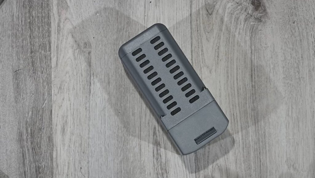
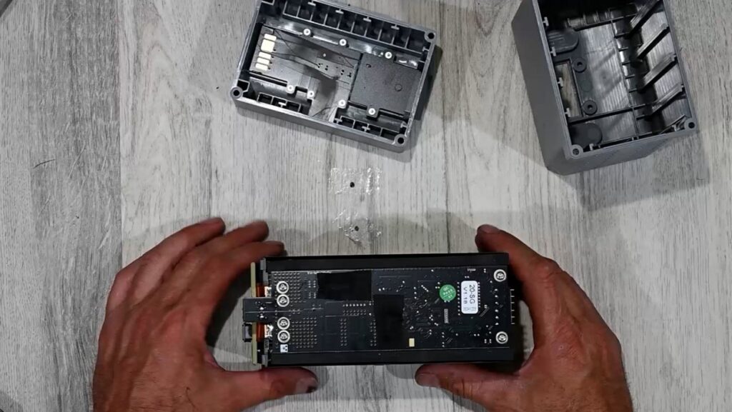
UniTree Go2 Quadruped Robot Dog Battery Pack
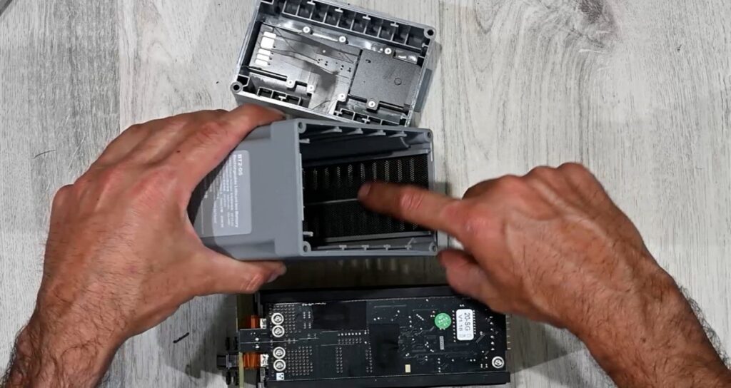
The Go2’s battery pack reflects a well-balanced approach to mechanical design, electrical safety, and user ergonomics. It is a swappable unit built around high-density 18650 lithium-ion cells and is designed for rapid replacement in the field without tools. A toolless pinch-and-release latch system enables the user to remove or insert the battery with one hand, while the dual latches automatically snap into place upon insertion, ensuring a mechanically secure and electrically sound connection. This mechanism supports quick turnaround during field testing or extended deployments.
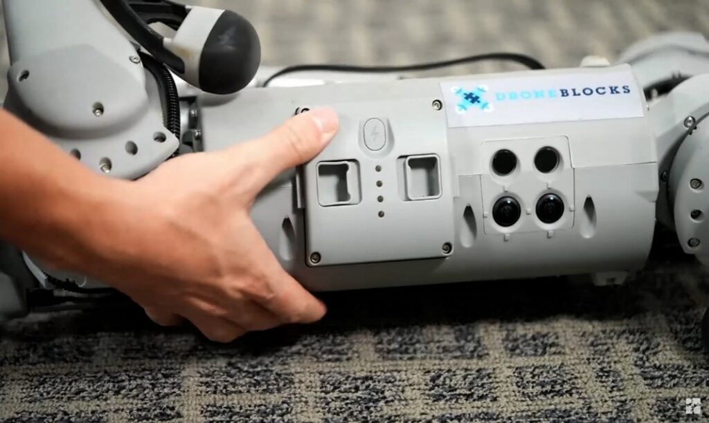 Battery Pack Being Inserted into the Go2
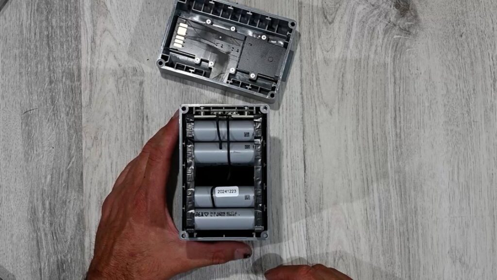 Cylindrical battery cells inside the Go2’s battery pack
Internally, the pack uses a custom battery management system (BMS) mounted on a rigid PCB. The BMS oversees charge and discharge balancing, cell-level voltage and temperature monitoring, and protection circuitry. A flexible printed circuit board connects this BMS to the battery’s status display, enabling external visibility of charge status without opening the unit.
The cylindrical cells are arranged compactly, with thick copper bus bars or leads interconnecting them. These conductors are further reinforced with Kapton-like tape to isolate against electrical shorts and to reduce vibration fatigue during high-dynamic locomotion. The use of robust insulation materials and routing discipline reflects an understanding of shock and motion-induced wear, which is especially important in mobile robotic platforms.
Structurally, the enclosure looks like a single-shot injection-molded plastic housing. It is molded with detailed textures and contours that mimic a two-piece design, reducing part count and improving durability. The casing includes an external mesh-like venting screen and internal polymer barriers that protect against debris ingress while allowing for heat dissipation. These features contribute to thermal stability and reliability in environments where dust, dirt, or moisture might otherwise compromise safety or performance.
Leg Architecture and Mechanics
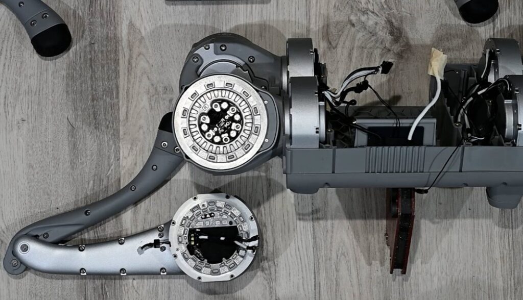 Inside view of the Unitree Go2 Quadruped Robot Dog Leg
Each of the Go2’s four legs feature a fully integrated electromechanical assembly with three actuated joints, delivering 3 degrees of freedom per leg: shoulder roll (abduction/adduction), shoulder pitch (forward/backward swing), and knee extension. This configuration supports dynamic gait control, omnidirectional movement, and terrain adaptation across both structured and unstructured environments.
Actuation and Transmission:
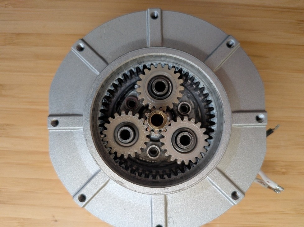
Each joint is driven by a compact BLDC motor coupled to a high-efficiency planetary gearbox, estimated to have a reduction ratio near 6:1. This provides the necessary torque amplification while maintaining a slim form factor. The motor and gearbox assembly are directly mounted into a custom-machined aluminum housing, designed to optimize structural stiffness and minimize compliance under load.
Position Feedback and Control:
Joint position sensing is handled by magnetic pole ring encoders integrated into each motor shaft. These absolute encoders provide precise angular feedback without contact, enhancing reliability in dusty or high-vibration environments. Each actuator contains a localized motor control board mounted directly to the housing, supporting:
- Serial communication passthrough
- Power distribution
- Encoder signal processing
- Local commutation and current control
The three joints per leg are electrically daisy-chained using a simplified wiring harness that allows for both signal and power delivery through a single compact connector. This modular architecture reduces overall cable complexity and simplifies the mechanical interface.
 View showing how the leg interfaces with the shoulder features
Mechanical Structure and Serviceability:
The leg modules are designed for rapid field replacement. Each leg attaches to the main body through a minimal set of mechanical and electrical fasteners, enabling full leg swaps with only a few connectors. The interfaces are precision-machined to reduce backlash and maintain joint alignment. Torque loads are transmitted efficiently across machined shoulder pivots and reinforced mounting brackets that tie into the central chassis structure.
Flex Cable Routing
The Go2’s internal cable routing architecture reflects a high degree of mechanical and electrical integration, particularly at the hip joints where dynamic flexing occurs. Each leg’s motor wiring is managed using a coiled flex cable that wraps around a central aluminum hub, enabling full joint articulation while minimizing mechanical strain and electrical fatigue.
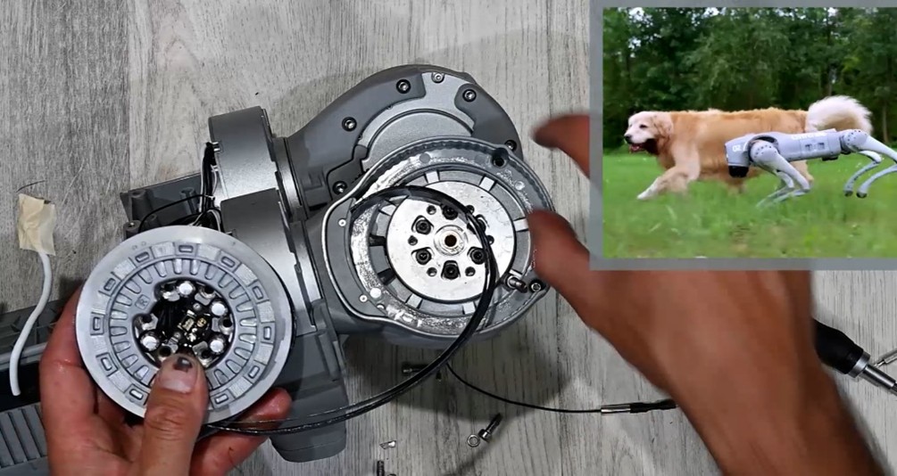 Flex cable wrapped around aluminum hub, supported by spring steel
The flex circuit is supported by a stamped and formed spring steel spine that maintains a consistent bend radius and distributes stress evenly across the cable’s length. This prevents the conductors from kinking or delaminating during repetitive motion. The aluminum hub is post-machined with precision cable routing channels and grooves to anchor the flex and maintain consistent alignment throughout motion cycles.
Lubricant is carefully applied along sliding surfaces to reduce friction between the flex jacket and surrounding components. This both protects the outer insulation and prevents heat buildup during repetitive motion. The flex cable is anchored at both ends using clamping features or epoxy reinforcement to prevent wire pullout or solder joint fatigue.
Unlike typical consumer robotics where cable routing often relies on loosely constrained harnesses or simple wire loops, this approach represents a more industrial-grade solution. It is engineered to support thousands of high-dynamic load cycles in a compact envelope, critical for quadrupeds expected to operate in rugged environments with frequent leg articulation.
This cable management strategy not only improves long-term reliability and serviceability but also reduces EMI risk and ensures signal integrity for motor control and feedback across the legs.
Motor Teardown & Modeling
To better understand the capabilities and internal architecture of the UniTree Go2’s custom actuators, our engineering team performed a full reverse-engineering teardown and modeling of one of the leg motors. This motor integrates the powertrain, control electronics, and sensing elements into a single compact module and serves as the foundational unit for each of the robot’s 12 actuated joints.
Mechanical & Electrical Analysis:
- The gear train was disassembled to reveal a multi-stage fine-pitch planetary gearbox, estimated at approximately a 6:1 reduction ratio. The design uses hardened steel gears and dual ball bearings to support high torque loads with minimal backlash.
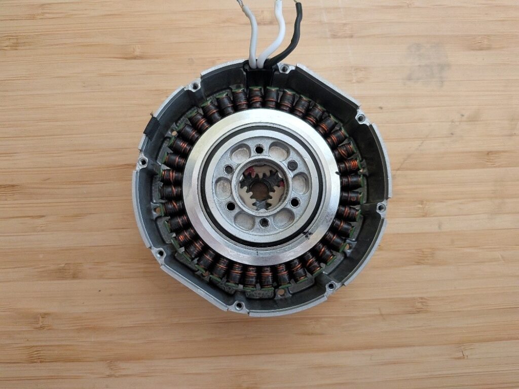
- The stator was separated from the rotor, which features precision-balanced permanent magnets and high fill-factor windings, optimized for high torque density in constrained spaces.
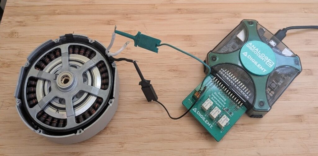
- Electrical properties were characterized through direct measurement:
- Phase-to-phase resistance
- Phase inductance
- Back-EMF constant (Ke)
- These parameters allowed us to derive an estimate for the torque constant (Kt) and dynamic characteristics such as bandwidth and thermal performance under load.
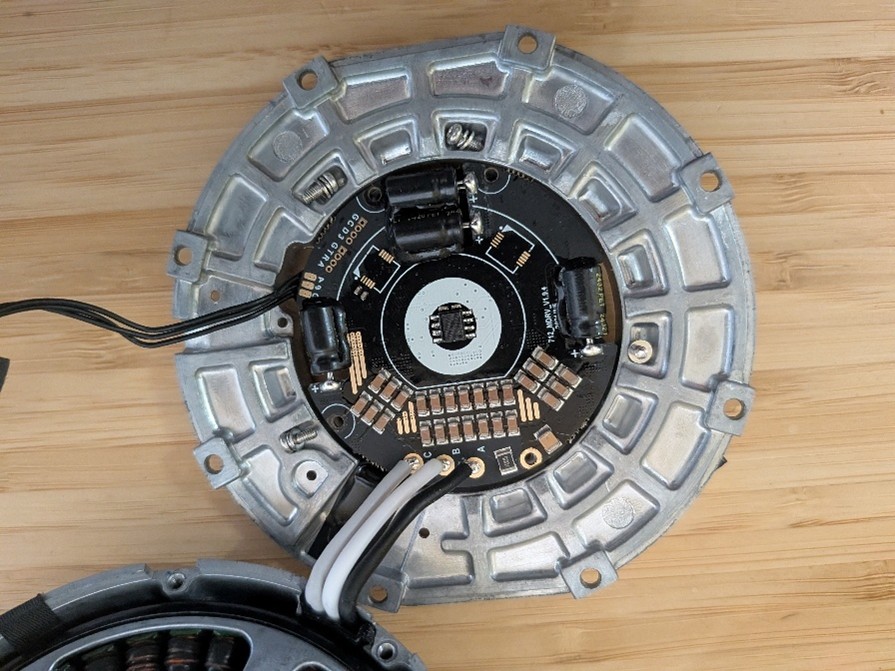
Integrated Control Electronics:
- A custom motor driver PCB is embedded within the actuator housing, directly interfacing with the motor windings and the onboard magnetic absolute encoder (likely using a pole-ring sensor with Hall or AMR-based feedback).
- The board supports Field Oriented Control (FOC), using real-time current sensing and position feedback for precise closed-loop operation.
- Power is delivered through dual banana plug terminals, while data and control are passed via Molex PicoBlade connectors using a serial daisy-chain protocol.
- The control board features multi-stage voltage regulation, likely supporting 12V logic and gate drive levels from a 24–36V input source.
System Modeling:
From these measurements, we created a full dynamic DQ model (d–q axis modeling) of the motor, capturing torque generation, current dynamics, and voltage constraints. This model enables accurate simulation of joint behavior, including thermal loading, saturation effects, and position/velocity control bandwidth. The resulting data is critical for:
- Virtual prototyping of leg dynamics
- Control loop design (e.g., PD or model-predictive control)
- Evaluating response under dynamic gaits and terrain interactions
Key Takeaways:
- Highly integrated, compact actuator design tailored for quadruped robotics
- Excellent use of embedded electronics for real-time control with minimal wiring
- Suitable as a reference for similar applications requiring low-latency, high-precision torque control in space-constrained environments
This level of teardown and modeling not only reveals the engineering sophistication of UniTree’s actuators but also provides a valuable benchmark for anyone developing legged robotic systems or high-performance joint modules.
 Simplexity Senior Mechanical Engineer, Luis Elenes and Technician/Machinist, Jason Glaser reverse-engineering the UniTree Go2 Quadruped Robot Dog
Conclusion: UniTree Go2 Quadruped Robot Dog Teardown
We hope you enjoyed learning insights behind the design of the UniTree Go2 quadruped robot dog. The design demonstrates an impressive blend of thoughtful engineering, modular design, and cost-effective manufacturing strategies. From its highly integrated actuators and field-replaceable leg assemblies to a thermally optimized electronics system and ruggedized LiDAR integration, every aspect reflects a deep understanding of the challenges in legged robotics. While marketed as a consumer product, the Go2 clearly functions as a capable development platform, offering insights, inspiration, and real-world applicability for engineers exploring advanced robotic mobility.
If you are developing a robotic system and could benefit from some additional engineering help, please contact us today.