At the heart of Quadraped robots like the Unitree Go2 Robot Dog are compact, powerful, and highly integrated joint motors. But what exactly is inside these “robot muscles”? And more importantly, if you wanted to source an equivalent replacement, or determine if these motors would be suitable for your custom application, what would you need to know?
To answer these questions, we recently performed a complete teardown of one of the Go2 Joint Actuators as part of a reverse engineering exercise. You can read the full blog and watch the teardown video here. While the full teardown will cover the entire Unitree Go2 Robot Dog, the blog below will focus specifically on the motor.
Overview Go2 Motor Teardown
The Why: Goals of the Unitree Go2 Motor Teardown
The purpose for this teardown was threefold:
- Sourcing an Equivalent: These integrated joints are often proprietary and expensive. By understanding the core components (motor, gearbox, driver), we can identify and source equivalent off-the-shelf parts to build a comparable, lower-cost, or more customizable actuator.
- Unlocking FOC Control: To properly drive the motor using a modern Field-Oriented Control (FOC) driver, we need to know its fundamental electrical parameters. This teardown is the first step in determining the pole-pair count, phase resistance, inductance, and back-EMF constant.
- Enabling Dynamic Modeling: For advanced robotics, simulation is key. By deriving the motor’s single-phase equivalent parameters, we can model the robot’s dynamics, predict performance, and correctly size system components like the main power supply.
The What: Key Characteristics and Specifications
During the teardown, the following build details, characteristics, and functional specs are to be identified:
- Material component elements comprising the Integrated Joint Actuator system, such as:
-
- External mechanical/electrical interfaces
- The presence of integrated motor driver electronics
- Output drivetrain gear ratio
- Motor construction, slot/pole configuration, and included commutation and positioning feedback hardware
2. Key functional and electrical motor specifications typically found in motor datasheets such as the motor pole-pair count, and line-line and single-phase speed/torque/back-emf constants, which are used for:
-
- Sizing an appropriate DC power supply for target load limits
- Determining theoretical performance limits such as max speed
- Performing basic efficiency and power calculations, as required inputs to a typical FOC motor driver
3. Derived FOC q-axis parameter representations of those specs that are required for simulating transient motor dynamics and power consumption in your modeled application.
(See The Result: Summary of motor specs for the complete list of these specs and their determined values tabulated at the end of this blog)
The How: The Teardown Process Documented
Disassembly – The Joint Externals
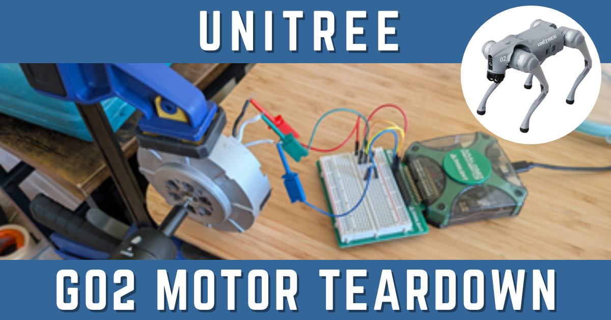
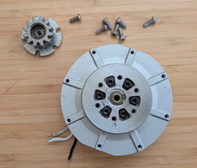
The joint, once removed from the Go2 Robot Dog, is shown here – and the external mechanical and electrical interfaces can be inspected without disassembly.
Assembled Joint Motor
The motor housing measures approximately 96mm in diameter and 40mm deep, with flats on 2 opposing sides and has an external mounting hole pattern on its drive/output face only.
A custom pinion-gear-plate appears to be this joint’s output drive interface.
The housing has a separable back-shell with an integrated electronics PCBA mounted within it with several cables and wires exiting the housing. They provide electrical and communication interfaces for the joint.
Specifically there are 2x single-channel wires with drone-style banana-plug/jack terminals likely providing the DC Bus voltage to the board, and 2x small 3-pin (likely Molex pico-clasp) connectors. They presumably provide a primary serial interface for a dedicated controller on the PCBA, and the second possibility is that they provide a convenient secondary serial interface to simplify daisy-chaining communication to/from other joints.
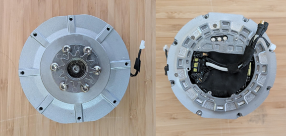
Disassembly – The Integrated Driver Board
The housing back-shell can be unfastened and partially lifted to reveal the underside of the integrated electronics board along with the ‘back-shaft’ side of the motor internals.
Once exposed, the electronics board was solely connected to the motor via the 3x motor leads running from the motor-stator-coils to the large vias on the board conventionally labelled ‘A’, ‘B’, ‘C’.
The motor leads can (and must) be de-soldered from the driver electronics to allow subsequent characterization measurements to be performed on the motor in isolation – and once detached we can get a closer look at the integrated electronics PCBA.
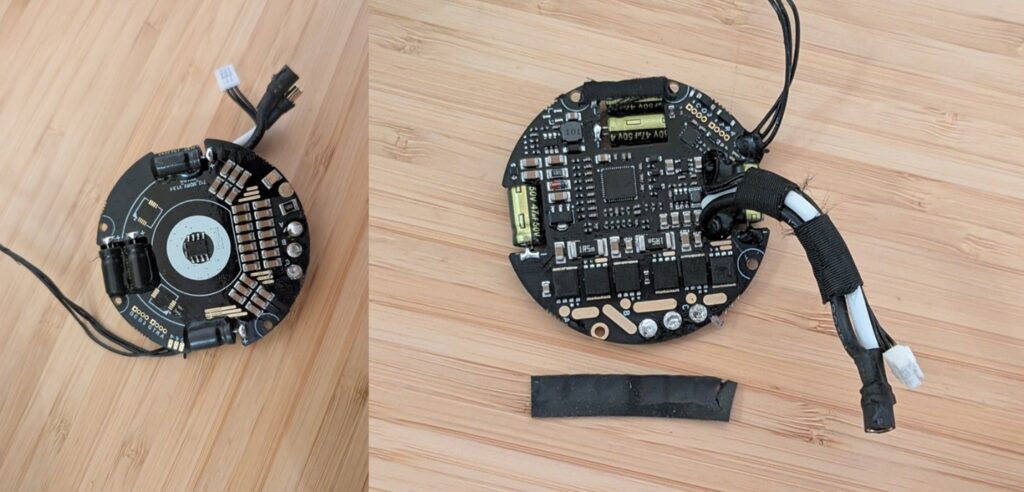
Although the integrated circuits (ICs) on the driver board have been removed – we can infer the following functional components:
- Position sensing and commutation: An integrated circuit (IC) chip is present on the motor-side of the board centered directly over the rotor-back-shaft. A quick check with a magnet confirms that the ring-feature visible on the rotor-back-shaft is a diametric ring magnet – confirming that the IC-chip centered above it is an absolute magnetic encoder IC which provides high resolution absolute position feedback.
- Power Stage: 6x ICs conveniently arranged next to the motor-leads terminals are identified as six power MOSFETs, the standard configuration for a three-phase bridge inverter. A thermal pad was installed over them ensuring they effectively dissipate heat into the motor’s back-shell.
- Motor Controller: A central IC, presumably a microcontroller (MCU), is responsible for handling external communication, processing position sensor data, and running the motor control algorithm (almost certainly FOC).
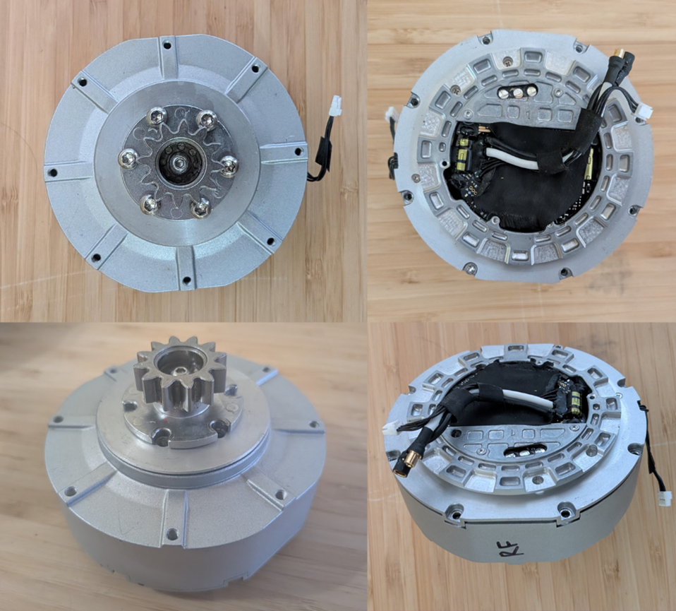
Disassembly – The Transmission
Removing the pinion-gear reveals a general-purpose interface for the joint’s drive output that rotates about a central shaft running back to the motor’s rear rotor. This is the transmission’s input shaft, which appears to be coupled by means of an internal reducing geartrain.
The output flange can be further disassembled to reveal an integrated planetary gearbox which translates the motor’s high speed into lower-speed, higher-torque, and allows for higher resolution position sensing from the motor’s absolute encoder – the following details and characteristics were identified:
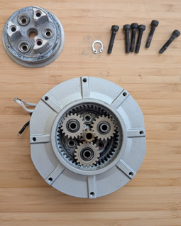
- Topology: The motor’s rotor shaft drives the central sun gear. This meshes with three planet gears, which in turn roll against the inside of a stationary ring gear. The output is taken from the rotating planet carrier.
- Gear Ratios: By counting the teeth, we find:
- Sun Gear (N_sun): 9 Teeth
- Planet Gears (N_planet): 19 Teeth (each)
- Ring Gear (N_ring): 47 Teeth
- (derived as N_ring = N_sun + 2*N_planet)
- Reduction Ratio: With the ring gear fixed, the reduction ratio is calculated as:
- Ratio = 1 + (N_ring / N_sun) = 1 + (47/9) ~= 6.22 to 1
In other words – for every 6.22 rotations of the motor, the output shaft rotates once, and the available torque is multiplied by approximately the same factor (minus efficiency losses).
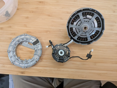
Disassembly – The Motor
The core of the Joint Actuator is the three-phase brushless DC (BLDC) motor.
With the motor shaft decoupled from transmission output flange the rear outer can (the “rotor” housing the magnets, aka the poles) can be separated from the stationary inner section (the “stator” containing the motor coils, aka the slots) and key construction and configuration details can be inspected.
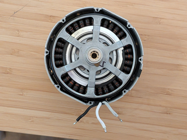
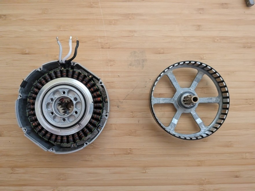
- Construction: The motor is an out-runner design, meaning the rotor with magnets rotates externally around the stator.
- Configuration Parameters:
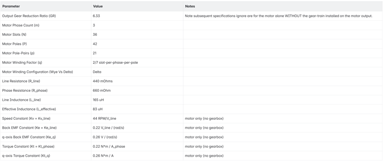
- m = Number of phases = 3
- N = Number of slots = 36
- P = Number of poles = 42
- q = Winding Factor = N / (P * m) = 36/42/3 = 2/7 “slots-per-pole-per-phase”
- Since q is a non-integer, this motor uses “Fractional-Slot-Winding” (as opposed to “Integer-Slot-Winding”) where the number of slots is not an even multiple of the poles and phases. This results in reduced cogging torque and a smoother back-emf as the motor rotates through its electrical rotations.
- In other words, the winding pattern of the coils repeats every 7 poles, and within that repeating unit, there are 2 slots assigned to each phase. Consequently, since there are 42 poles in total, the winding pattern is repeated a total of 42/7 = 6 times over the full 360 degrees of the stator, with each pattern consisting of 36 total-slots / 6-repeats = 6 slots per repeating unit
- p = Number of pole-pairs = P/2 = 21
- Winding Configuration (Wye vs Delta) = ???
- A key parameter that cannot be determined directly by visual inspection alone. See next section
- Configuration Summary: There are 36 slots (the stator coils of wire) and 42 poles (or 21 pole-pairs, 42 magnets alternating North/South in the rotor). The motor, therefore, has a 36N42P configuration with a high pole-pair count and fractional winding factor, yielding reduced cogging torque throughout its angular range compared to lower pole-pair or integer wound motors with otherwise equivalent electrical specs.
Measurements – Motor Winding Configuration: Wye or Delta
Several critical motor functional and electrical parameters can be measured directly (i.e. the line-line resistance between two motor leads) However, determining their single-phase-equivalent values can only be accomplished with knowledge of the Motor Winding Configuration.
Not to be confused with the Slot-Pole configuration (36N42P) or the winding factor (q=2/7 slots-per-pole-per-phase).
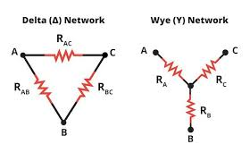
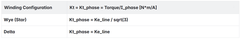
The motor winding configuration specifies whether the stator coils are wound in a Wye (aka Star) or Delta pattern, and directly impacts the calculations required to convert from easily measurable line-line values to single-phase (and q-d axis) equivalents.
Once the winding configuration is known we can establish the relationships between line-line and per-phase electrical parameters as such:
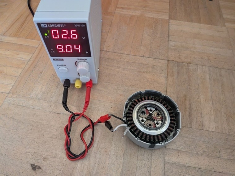
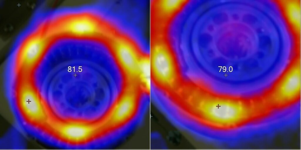
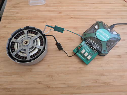
A simple method for determining the winding configuration is to use a thermal imaging camera to view the stator coils while driving a voltage across two of the motor leads, leaving the 3rd disconnected.
For a Wye wound motor, current will pass through coils associated with 2 phases in series and heat them up while coils associated with the third phase should remain cool.
For a Delta wound motor, current will pass primarily through coils of a single phase (while a small amount will pass through the others in parallel).
Since our motor has a 36N42P configuration (with winding factor, q, of 2/7). We expect 6 repeating units of coils around the full 360 degrees of the motor – with each repeating unit having 6 coils total (2 per phase).
So, we expect to see 6 hot spots total regardless of Wye/Delta winding, but with either 4 of 6 coils heated (Wye) or 2 of 6 coils heated (Delta).
With our motor hooked up to a benchtop power supply unit (PSU), and the voltage increased to drive a line-current of ~8-9 Amps, thermal images were captured. The resulting heat pattern shows the expected 6 hot spots, each appearing to cover 2 of 6 coils.
The motor therefore has a Delta Winding Configuration.
Measurements – Line Resistance and Inductance
The line-line resistance, R_line, and inductance, L_line, can be directly measured between any 2 of the exposed motor leads. Ideally the result should be consistent regardless of the pairing (i.e. A->B = A->C = C->A).
The R_line values for BLDC motors are typically quite small, < 1 ohm, and so a typical digital multi meter (DMM) or ohmmeter may not have sufficient resolution to perform the measurement accurately.
But by using an LCR meter or impedance analyzer, both the R_line and L_line can be measured directly and accurately across any two motor leads.
Hooking up our motor to an impedance analyzer the R_line and L_line were found (and confirmed to closely match across each motor-lead pairing) as follows:
- R_line ~= 440 mOhms
- L_line ~= 165 uH
The equivalent phase values are therefore:
- R_phase = 3/2 * R_line ~= 660 mOhm
- L_effective = 1/2 * L_line ~= 83 uH
Measurements – Line Speed Constant and Back EMF
The velocity constant, Kv (sometimes called out as KV) is a critical functional parameter of 3-phase BLDC motors.
It is so critical, in fact, that for many BLDC motors on the market, it may be the only functional specification provided.
Kv relates the motor rotational speed to the voltage used to drive it in RPM/Volts.
More specifically, by convention, it relates the RPM to the line-line voltage, and unless specified otherwise:
Kv = KV = Kv_line = RPM/V_line
In essence, the higher the Kv value, the faster the motor will spin for a given input voltage under no-load conditions.
Kv is related to another critical motor parameter, the back-EMF-constant, Ke as:
Ke = 1/Kv = Volts/RPM
Which, also by convention, is typically given in terms of the line-line voltage but usually spec’d in SI-units:
Ke = Ke_line = V_line/RPM = V_line / (rad/s)
Ke relates the voltage generated by the motor to its rotational speed in V_line/RPM or (in SI units) V/(rad/s).
The faster the motor spins, the larger the back-emf-voltage generated, and the higher the Ke value (and thus lower Kv).
The Ke value can also be (almost) directly equated to the motor’s torque constant, Kt, which relates the torque output of the motor to the driving current (N*m/Amps).
The higher the Kt value, the more torque the motor will generate for a given input current.
But, more specifically, by convention, the Kt value is given in terms of the “phase current” and is equal Ke_phase, where Ke_phase relates to Ke_line and Kv_line depending on the winding configuration (Wye vs Delta) as presented earlier which simplify to:
From the above relationships, it can be seen that Kt and Ke are inversely proportional to Kv – the higher Kv value for a motor, the lower its Kt, and vice versa.
Motors intended for high-speed applications with high Kv have correspondingly low Kt and more effectively translate input drive power into high speeds with relatively low torque output.
While, low Kv motors (high Kt), more effectively translate input power into high-torques at low speeds.
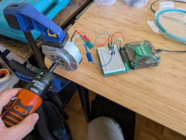
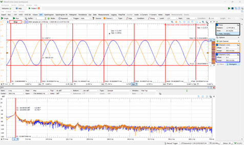
These values can be simply determined for a BLDC motor by back-driving the motor at some fixed speed (e.g. by using a drill), while monitoring the line-line voltage with an oscilloscope and comparing the frequency of voltage oscillations against the peak-peak voltage values.
As shown in the accompanying images, testing our motor resulted in a V_line of 2.15V when rotated at an electrical frequency of ~33.3Hz which corresponds to a mechanical angular rate of:
omega_motor = 2*pi * f_elec / pole-pairs = 2*pi * 33.3/21 = 9.96 rad/sec ~= 95 RPM.
from these values we get:
Kv_line = 95 RPM / 2.15V ~= 44 RPM/V_line
Ke_line = 2.15V / 9.96 rad/s ~= 0.22 V_line*s/rad
Kt_phase ~= 0.22 N*m/A_phase
Calculations – Steady State and Performance Limit Estimations
The driving equations for modelling a single-phase DC brush motor are:
- Mechanical Dynamics (Newton’s Second Law):
- J*alpha_m = Kt * I – b*omega_m – T_load
- (Torque from current minus friction torque minus external load torque equals inertial torque)
- Electrical Dynamics (Kirchoff’s Voltage Law):
-
- V = I*R + Ke * omega_m + L * dI/dt
- (Applied Voltage equals resistive drop plus back-EMF plus inductive drop)
For a three-phase BLDC motor, the fundamental physics is the same, but the control strategy is completely different.
If you were to apply a simple DC voltage across two motor leads, you would get an initial burst of torque that quickly fades as the rotor aligns with the new magnetic field, and the motor would come to a stop.
To keep it spinning, the motor driver must constantly adjust how each phase is energized to create a rotating magnetic field for the rotor to follow.
This means that the voltages and currents are no longer simple DC values. They are complex sinusoids that must be synchronized to the rotor’s position.
And so, it appears the simple DC motor model breaks down.
We can, however, still use the DC model directly along with our line and phase measurements to perform simple steady-state estimates, system sizing, and back-of-the-envelope calculations – i.e. cases in which we are looking at the boundaries of performance like:
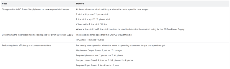
Calculations – Determining the d-q Model for FOC Control
To accurately model (and control) the three-phase BLDC motor, the FOC algorithm introduces the concept of the rotating d-q reference frame which transforms the 3 separate phase currents (I_A, I_B, I_C) into 2 new parameters (Iq, Id) that are dependent on the current rotation angle of the motor, with Iq representing the useful torque producing current, and Id representing the non-torque producing current.
The FOC algorithm attempts to maintain Id at zero while computing the corresponding phase current I_A, I_B, I_C from a single Iq set-point – effectively converting the complex 3-phase BLDC model into a simpler decoupled DC model.
The ideal FOC controlled BLDC motor can be modelled assuming that the d-axis current is perfectly zero – allowing all other ‘d-axis’ electrical to be ignored – leaving only the ‘q-axis’ components, and the resulting driving single-phase equations can be re-phrased in terms of the q-axis equivalent parameters:
- Mechanical Dynamics (Newton’s Second Law):
- T_q = Kt_q*I_q = J*alpha_m + b*omega_m + T_load
- Electrical Dynamics (Kirchoff’s Voltage Law):
-
- V_q = R_phase * I_q + Ke_q * omega_m + L_effective * d(I_q)/dt
By noting that omega_m = d(theta_m)/dt, and alpha_m = d2(theta_m)/dt2,
and establishing the relationship between q-axis and line properties as:
- Wye configuration:
- V_line = sqrt(2) * V_q = sqrt(2) * Ke_q * d(theta_m)/dt
- Kt_q = Ke_q = Ke_line / sqrt(2)
- Delta configuration:
- V_line = sqrt(2/3) * V_q = sqrt(2/3) * Ke_q * d(theta_m)/dt
- Kt_q = Ke_q = Ke_line / sqrt(2/3)
And thus, from our earlier measurements, we can determine the q-axis equivalent back-emf and torque constant values as:
- Ke_q = Ke_line / sqrt(2/3) ~= 0.26 V*s/rad
- Kt_q = Ke_q ~= 0.26 N*m/A
We can now fully model the transient dynamics of the 3-phase FOC motor across time and motor position with the motor parameters measured previously.
For instance, we could now measure the instantaneous power losses through the coils as:
P_loss = Iq * R_phase
(by solving for Iq using numerical integration on the above driving model equations)
The Result: Summary of Motor Specs
From the teardown we have determined the following key characteristics of the motor.
Conclusion: Unitree Go2 Motor Teardown
Our teardown of the Unitree Go2 joint motor uncovered the intricate design behind its compact, high-performance actuator. By analyzing its 36-slot, 42-pole BLDC outrunner motor, identifying a Delta winding configuration, and measuring key electrical parameters like resistance, inductance, and back-EMF constants, we now have a clear understanding of its construction and functionality. These insights enable precise Field-Oriented Control (FOC), accurate simulation using d-q modeling, and informed decisions when sourcing or designing comparable motors for custom applications.
If you would like to see the full teardown, check out our UniTree Go2 Quadruped Robot Dog Teardown!