Whether you’re developing advanced automation systems, a robotic system, or simply looking to streamline your industrial processes, there often comes a point when off-the-shelf PLC hardware just isn’t flexible or scalable enough. That’s where creating a CODESYS program for EtherCAT devices becomes invaluable. By leveraging CODESYS—a powerful software framework that can turn a standard Linux PC into a real-time, deterministic Soft PLC—you can control a wide array of EtherCAT-enabled hardware using standard Ethernet cabling, all from a unified, software-driven platform. This approach not only reduces costs and complexity but also allows for rapid development, live debugging, and seamless integration of diverse industrial devices, making it an ideal solution for engineers and organizations seeking both flexibility and high performance in their automation and robotics projects.
In this tutorial we will walk through the process of creating a simple CODESYS project from scratch using the CODESYS Integrated Development Environment (IDE ) – that once downloaded – converts your Soft-PLC into a stand-alone Human-Machine-Interface (HMI) for Monitoring and Controlling a single connected EtherCAT Slave Device.
The tutorial includes videos featuring key steps outlined in the accompanying text below.
What is CODESYS and How Does It Work?
CODESYS is comprised of two main components:
- The CODESYS IDE (Integrated Development Environment), which runs on a Windows computer and serves as the development and debugging environment.
- The CODESYS runtime, which runs on a Linux PC and turns it into a Soft PLC, also known as a “Virtual PLC”.
With the IDE, you can write, and monitor PLC programs and then download them directly to your Soft PLC, enabling live debugging and real-time control.
Introduction to EtherCAT
EtherCAT is an independent, high-speed communication protocol designed for industrial automation.
It uses a single master/multi-slave bus topology, allowing a master device (the Soft PLC) to communicate with multiple EtherCAT-enabled slave devices.
All communication occurs over standard Ethernet cables (RJ45 connectors), making wiring straightforward and cost-effective. Devices are typically daisy-chained, but the topology can be flexible, supporting branches and trees.
Each EtherCAT device is defined by an Electronic Slave Information (ESI) file, which tells the master how to communicate with it, eliminating the need for custom drivers for each device.
Walkthrough Video
A live video tutorial demonstrates:
- Starting from a blank CODESYS project
- Turning your Soft PLC into an EtherCAT master
- Loading ESI files for connected devices
- Performing real-time monitoring and control with a custom EtherCAT slave device (in this case, a waveform generator running at 250 Hz)
Key Steps: How to Create a CODESYS Program for EtherCAT Devices:
Start a New CODESYS Project
- Open the CODESYS IDE and create a new project targeting your Soft PLC.
Connect to the Soft PLC
- Use the IDE to connect to your Linux-based Soft PLC over the network.
Configure EtherCAT Master
- Add an EtherCAT master device in the project’s device tree.
Import ESI Files
- Load the appropriate ESI files for each EtherCAT slave device you plan to use.
Add and Configure Slave Devices
- Insert slave devices into the EtherCAT master’s device tree, referencing their ESI files.
Program Control Logic
- Write your PLC logic to interact with the EtherCAT devices (e.g., send control signals, read sensor data).
Download and Test
- Download the project to your Soft PLC and use the IDE’s live monitoring tools to debug and verify real-time operation.
(Optional) Export and Share
- Save your CODESYS project for future use or sharing with colleagues.
For those who prefer not to watch the video, see the walkthrough steps broken out into text and figures in the appendix at the end for you to follow along and complete the setup independently.
Final Output
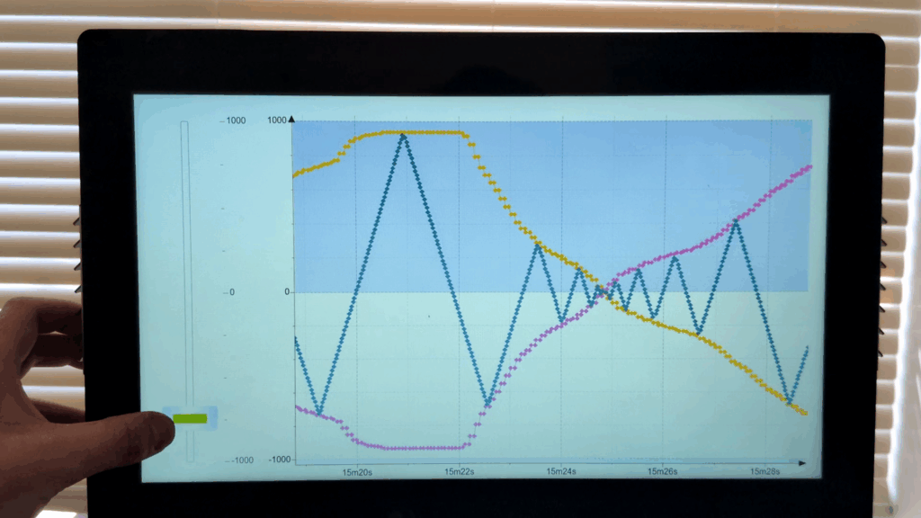
Depending on the connected ECAT Device* – the final result of the CODESYS project should look similar to this.
*Note – for this tutorial – I have connected a custom ECAT Slave Device developed previously by Simplexity for a past project that has been re-purposed into a simple controllable waveform generator for illustrative purposes.
The CODESYS program developed in the tutorial can be downloaded here:
codesys_ecat_tut_1.projectarchive
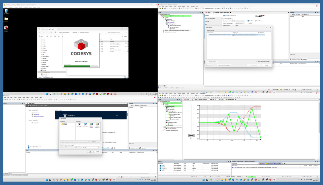
When viewing from the IDE:
When running on the Soft PLC directly:
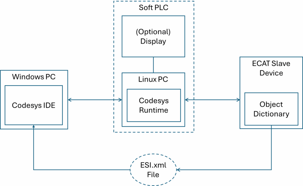
Hardware Setup – Before we start Code(sys)ing
Before we start generating the CODESYS project we will need the following setup:
1) A Windows PC with the CODESYS IDE installed
a. With the CODESYS EtherCAT stack and Visualization addon packages included in the installation
2) A Linux PC provisioned with the CODESYS Runtime to serve as our Soft PLC
a. With optional (touchscreen) display to provide the HMI
3) An EtherCAT Slave Device connected to the Soft PLC
4)The associated Electronic Slave Information (ESI) file available for our CODESYS program to reference
Conclusion:
In today’s rapidly evolving automation landscape, the ability to quickly adapt, scale, and integrate new technologies is more important than ever. Creating a CODESYS program for EtherCAT devices empowers engineers and organizations to break free from the limitations of proprietary PLC hardware, leveraging standard PCs and flexible, open communication protocols to control a diverse range of industrial equipment. This approach not only streamlines development and debugging but also reduces costs, simplifies wiring, and accelerates innovation. By mastering these tools, you and your team can respond to changing requirements with agility, build smarter systems, and stay ahead in a competitive market.
Appendix: CODESYS Project Generation Steps
For convenience, the complete set of steps taken in the walkthrough video have been compiled with text and figures below:
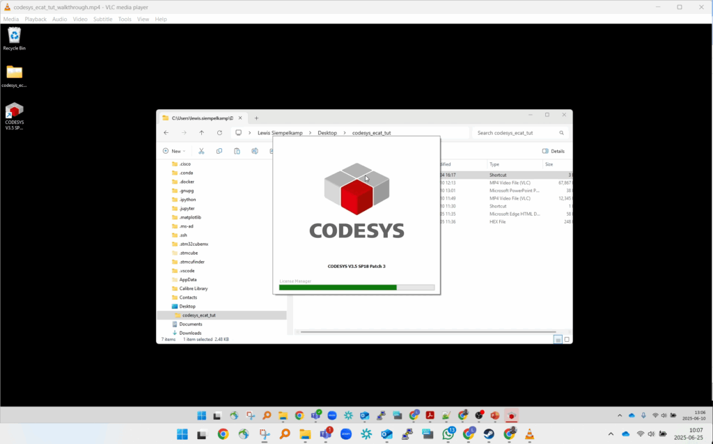
Launch CODESYS
From the Windows PC, Launch the CODESYS IDE application.
Create new project
From the CODESYS IDE, create a new Standard Project in your working directory.
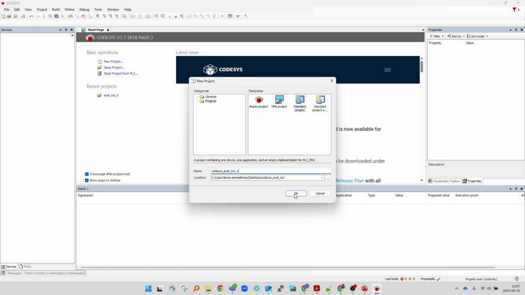
CODESYS IDE Toolbar → File → New Project
From the “New Project” dialog, select “Standard Project” and fill in the “Name” and “Location” fields then press “OK” to open the “Standard Project” dialog.
Select the “Device” Runtime appropriate for your Soft-PLC (CODESYS Control for Linux SL) from the dropdown field.
Select “Structured Text (ST)” as the specified programming language.
Press “OK” to generate the new minimal Standard Project.
Connect to the Soft PLC
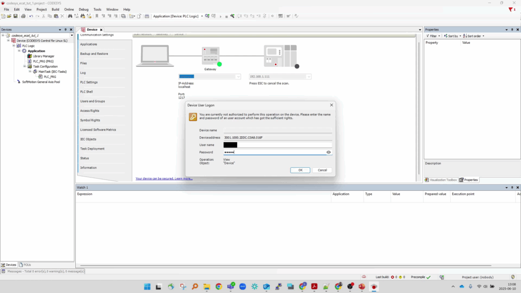
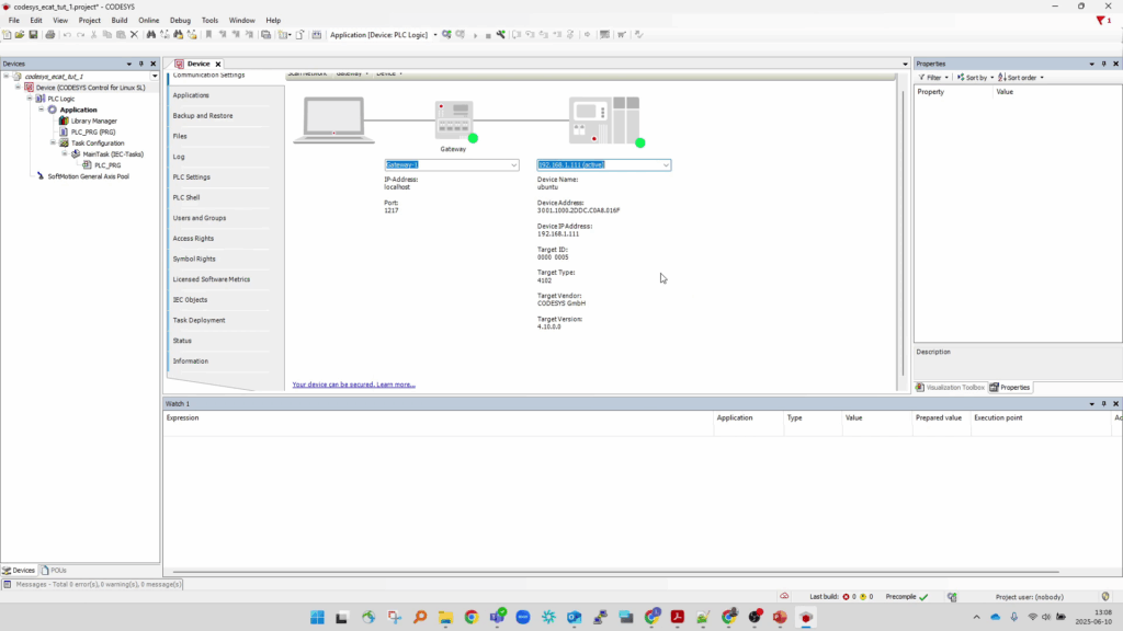
From the Device Tree (View → Devices), Double-click the “Device” node at the top of the tree to open the Device properties in the main viewport.
On the Device → Communication Settings tab, select the device path field and type in the static IP address associated with the connected Soft-PLC and press enter to open the Device User Logon dialog.
Enter the User name and Password and press OK to logon to the device.
Add EtherCAT Master Device Node
From the Device Tree, right-click the Device Node and select “Add Device…” to open the Add Device dialog.
From the dialog, expand the Fieldbusses->EtherCAT tree, and select EtherCAT Master (or EtherCAT Master SoftMotion) and press “Add Device”.
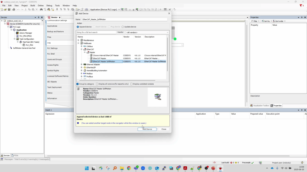
This will add two new nodes to the Device tree:
-
An EtherCAT Master node
-
and an associated EtherCAT_Task (IEC-Tasks) node
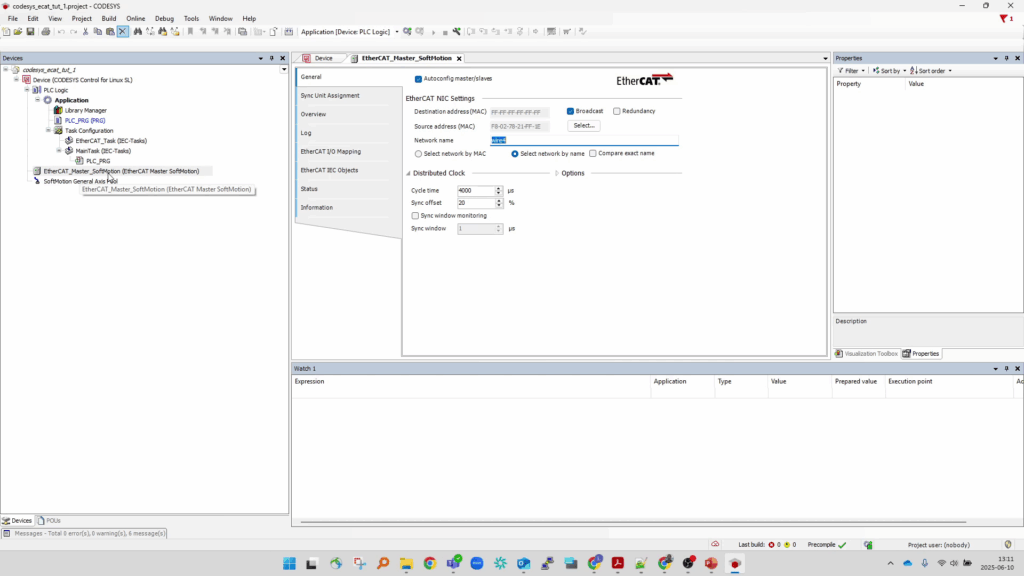
Configure EtherCAT Master Device
Double-click the newly generated “EtherCAT_Master” node in the device tree to open the associated properties in the main viewport.
From the EtherCAT_Master->General tab, press the “Select…” button to view the available Network Adapters on the Soft-PLC and select the adapter to be used as the EtherCAT Master’s primary port for connecting to the ECAT bus.
Select the “Select network by name” radio button.
Leave other settings as their default values.
Note that the “Cycle time” field also sets the associated EtherCAT_task interval period (in this case 4000us = 4ms = 250Hz)
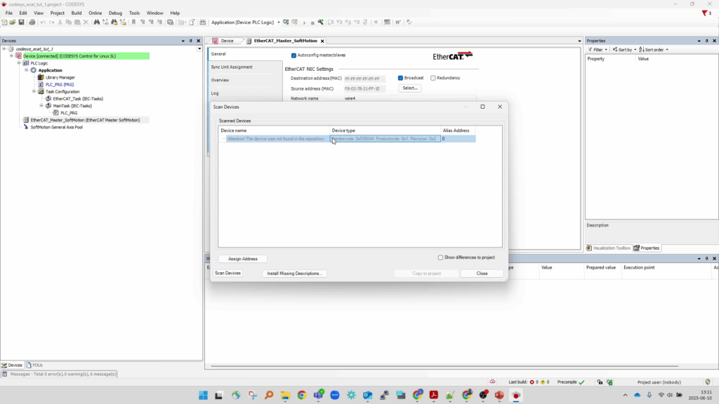
Scan EtherCAT bus for connected slave devices
With your EtherCAT slave device powered on and connected to the Network Adapter on your Soft-PLC set in the previous step:
Right-click the EtherCAT Master node in the device tree and press “Scan for devices…” to open the Scan Devices dialog.
Your device should show up in the Scanned Devices list.
Note – If this is the first time connecting to this particular device from CODESYS, the device should still be seen but may raise a warning that “The device was not found in the repository”.
This will be remedied in the next step – close the dialog and proceed.
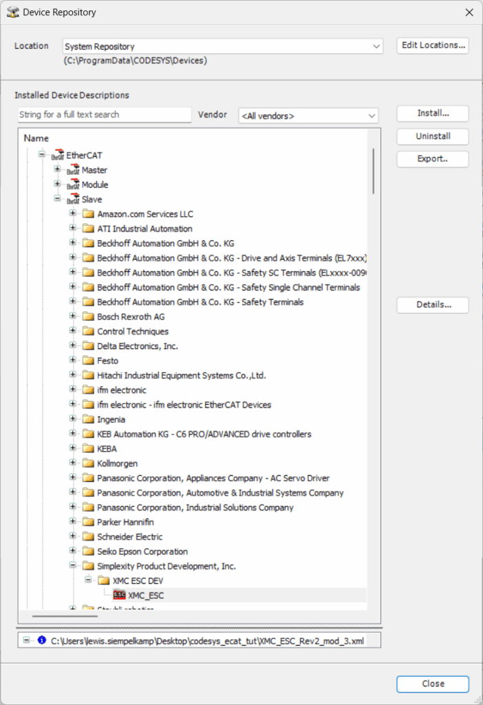
Add EtherCAT Slave Information File to CODESYS Device Repo
For CODESYS to properly interact with an EtherCAT Slave device, an alias of it must be first added to the CODESYS Device Repository using the associated Electronic-Slave-Information (ESI) file for the device. This is an xml file can be typically found and downloaded from the manufacturer page for the target ECAT device.
To do that open the Device Repository Dialog: CODESYS Toolbar → Tools → Device Repository…
From the Device Repository, press the “Install…” button, and then navigate to the ESI.xml file that you have for your device and select “Open”.
This will add a new entry to the Fieldbusses->EtherCAT->Slave under the name of the vendor for the device as shown.
Once installed, close the Device Repository Dialog and proceed.
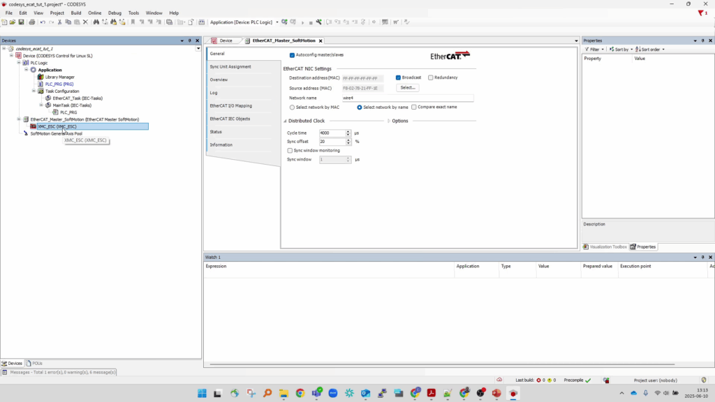
Add EtherCAT Slave Device to CODESYS Device Tree
With the EtherCAT slave device installed in the CODESYS Device Repository, re-scan the EtherCAT bus (right-click the EtherCAT_Master node in the device tree → Scan for Devices…).
From the Scan Devices dialog that opens, the connected slave device should now show up with its name populated properly without warning.
Select the device and press “Copy to project”, to create a new node in the device tree under the EtherCAT_Master node.

Setup PDO mapping and bind global variables
Double-click the new EtherCAT Slave Device node to open its property pane in the main viewport.
Select the “Process Data” tab to view the default Process Data Object (PDO) mapping for the device.
The “Outputs” pane will display the “Rx PDOs” (those that are received BY the ECAT-Slave FROM the ECAT-Master) and the “Inputs” pane will display the “Tx PDOs” (Those that transmitted FROM the ECAT-Slave TO the ECAT-Master) streamed in/out on each cycle tick of the EtherCAT master task.
Select the “EtherCAT I/O Mapping” tab to display the table of variables associated with the Rx/Tx PDOs.
Under the Variable column, type in a new (or existing) global CODESYS variable name for each PDO that the program should have access to. This binds these PDO values to variables that can then be interacted with from program elements directly.
Note the “Mapping” column field for each row which indicates if the Variable is bound to an existing or new variable.
IMPORTANT – from the “Always update variables” dropdown field – select “Enabled 1 (use bus cycle task if not used in any task”. If this is left at its default value, the global variables will only update if they are explicitly called by other CODESYS tasks. For the purpose of this simple CODESYS project, we wish to have these variables updated every EtherCAT bus cycle.

Download and run CODESYS Project on Soft PLC
Now save and compile the project so that it can be downloaded to the PLC.
Save the project: Toolbar → File → Save Project.
Compile the project: Toolbar → Build → Generate Code
“Download” the CODESYS project to the connected Soft-PLC: Toolbar → Online → Login
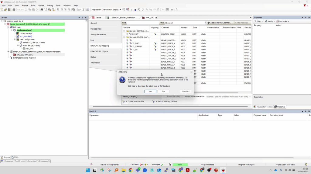
This should open a dialog asking to confirm that you wish to overwrite the PLC with the latest code.
Press Yes to start the download.
When first downloaded, the program is loaded in a stopped-state.
Press the triangular “Play” button (or Toolbar → Debug → Start) to start the program.
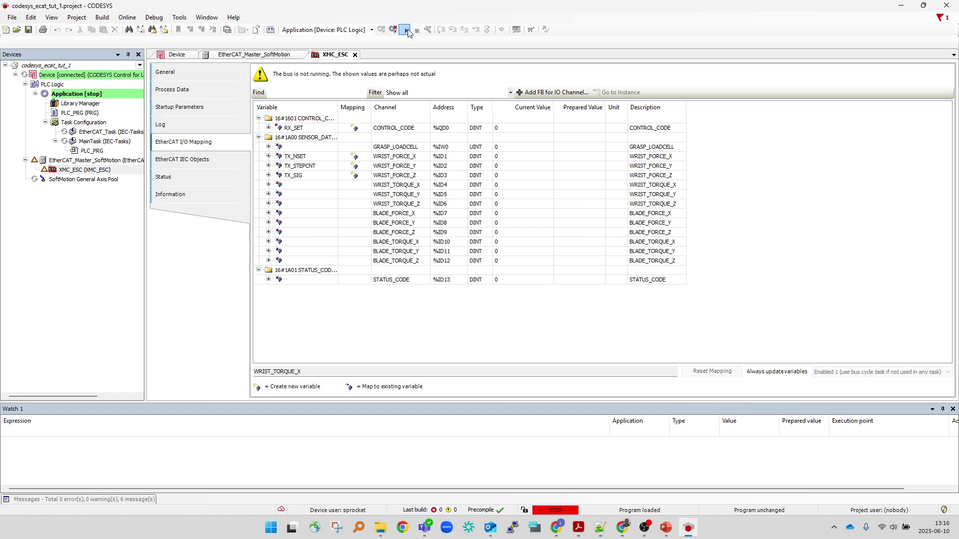
View live PDO output
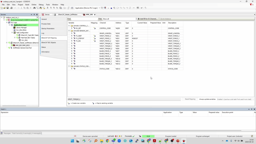
Once the program is running, the EtherCAT_Master and child slave nodes should show a green-connected icon next to their entries indicating that the EtherCAT bus is up and running.
Open the slave node’s main property pane back the “EtherCAT I/O mapping” tab.
The live PDO values should automatically begin streaming and their “Current Value” fields should be updating.
Create watch list with global variables
To immediately interact with the newly bound global variables for these PDOs, a watchlist can be created allowing the user to read/write values manually from the IDE while connected to the PLC.
This can be done while the program is running live without the need to re-build/re-download the program.
Open a new watchlist: Toolbar → View → Watch → Watch1
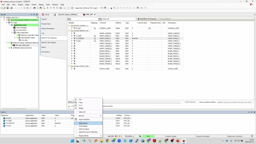
And from the Watch1 pane which is opened, populate the “Expression” field with the name of each Global variable created in the previous step.
The variables “Value” fields should show the live streamed value for each.
For the Output variables (the “Rx PDOs”), the values can be updated by entering new values in the “Prepared value” column, and then right-clicking and pressing “Write Values”.
In this manner, the CODESYS IDE can be used as a debug terminal to immediately Monitor and Control the connected ECAT device without any additional programming.
Create trace with global variables
To better view the live stream of the Rx/Tx PDOs a Trace object can be created in the program.
This can also be done live, while the CODESYS IDE is currently logged into the PLC running the program.
With the program running, from the device tree, create a new Trace node under the Application node and bind it to the EtherCAT_Task:
Device Tree → Right-Click Application Node → Add Object… → Select Trace…
From the “Add Trace” dialog that opens, enter a name for the Trace, and select “EtherCAT_Task” from the Task dropdown and press “Add”.
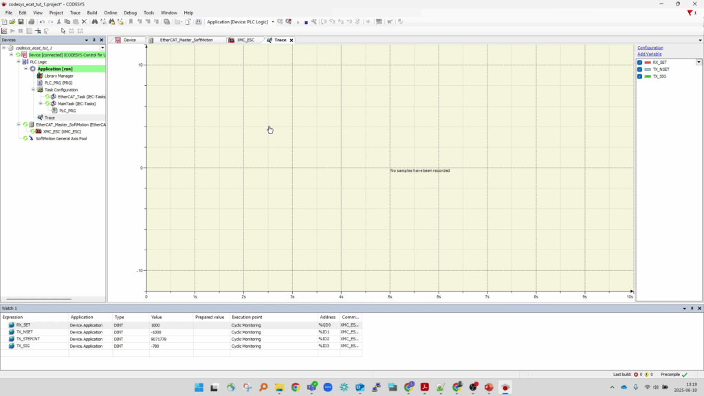
This will create the new Trace node and open the Trace viewer in the main IDE viewport.
For each global variable that was bound to the PDOs:
Press “Add Variable” to open the “Trace Configuration” dialog, and type in the associated Variable name, then press “OK”.
Monitor and Control from PLC
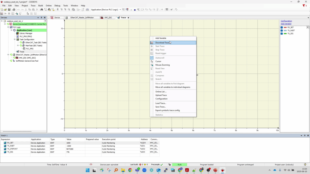
Once all variables have been added to the Trace Configuration, the trace can be made to start sampling their real-time values by write clicking the plot-view and selecting “Download Trace”.
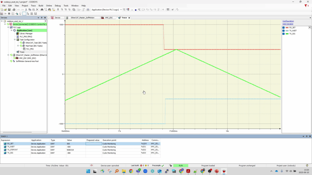
From the watchlist, you can continue to adjust the Output variables (the “Rx PDO” values) and see the live values of that and the other variables update in both the watchlist and on the trace plot.
With the program still running, the project can be saved to ensure the Trace configuration is preserved.
Toolbar → File → Save Project.
At this point we have a bare-minimum CODESYS project that when run on the Soft-PLC and ALSO connected from the PC running the CODESYS IDE allows us to Monitor and Control a connected EtherCAT slave device’s PDOs to verify it is connected and behaving as expected.
Add visualization element to CODESYS Project
To enable the Soft-PLC to serve as a stand-alone Human Machine Interface (HMI) for the connected EtherCAT device WITHOUT requiring a separate PC with the CODESYS IDE connected – we need to build a graphical interface that can then be interacted with from a display connected to the PLC directly.
To do this we will create a new Visualization object in the CODESYS project and populate it with some widgets to monitor and control the PDO variables.
From the CODESYS IDE – Log out of the running PLC program:
Toolbar → Online → Logout
Save your project if not done so already:
Toolbar → File → Save Project
Create a new Visualization Object node in the device tree:
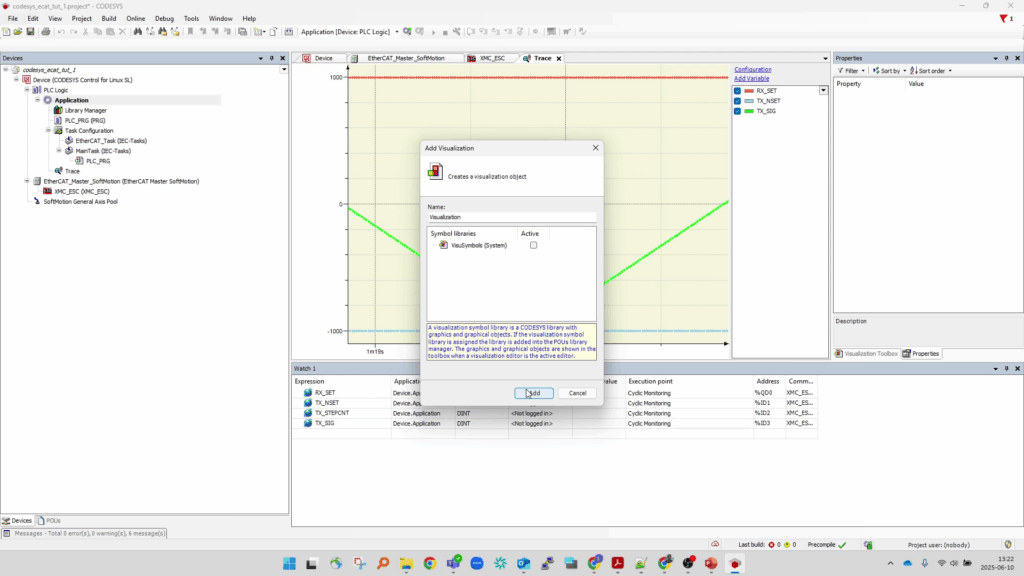
Device Tree → Right Click Application Node → Add Object → Select Visualization
And from the “Add Visualization” dialog that opens, press “Add”
This will generate a new Visualization node in the device tree (along with a new VISU_TASK (IEC_Tasks) node, and a Visualization Manager node – these can be ignored)
Add widgets to visualization
Double-click the new Visualization node to open its editor in the main viewport.
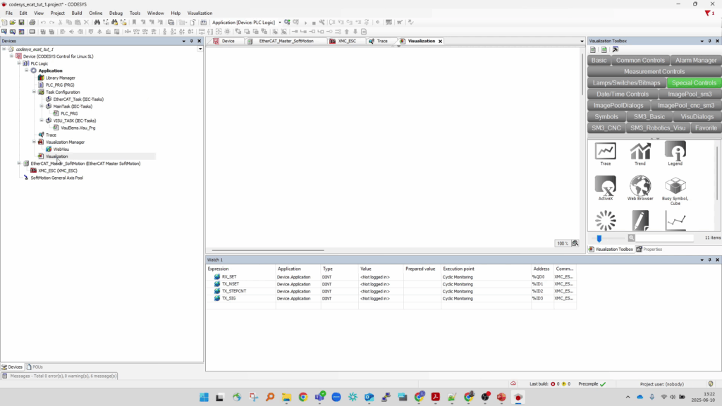
Note the Visualization Toolbox pane that opens to the right of the main canvas.
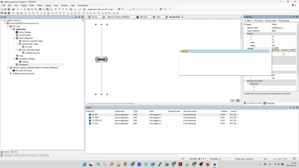
First – we’ll add a “Slider” widget to bind to the Global Variable associated with our ECAT device’s Rx_PDO, so that we can easily write out new new values to it from the visualization:
From the “Common Controls” tab of the Visualization Toolbox, select “Slider” and drag it onto the canvas.
Scale and rotate the slider so that it’s vertical and sized appropriately.
Select the slider widget on the canvas so that its “Properties” pane opens up.
Find the “Variable” field and enter the name of the Global variable associated with the Output/Rx_PDO as shown:
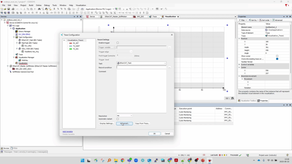
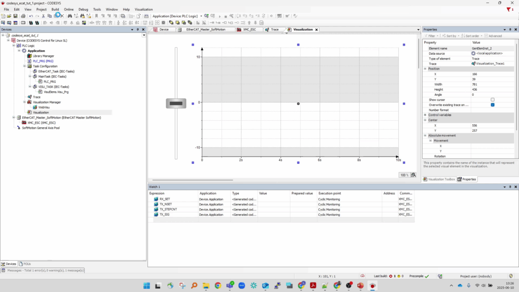
Next – we’ll add a “Trace” widget to display a live plot of all of the Global Variables much like we did earlier using the Trace Node object:
From the “Special Controls” tab of the Visualization Toolbox, select “Trace” and drag it onto the canvas next to the slider.
Right click the Trace widget, and select “Configure Trace”.
From the “Trace Configuration” dialog that opens, press “Copy from Trace…” and select the Trace Node object that we created previously – this will copy over all of the settings and mapped variables from the previously configured Trace node as shown:
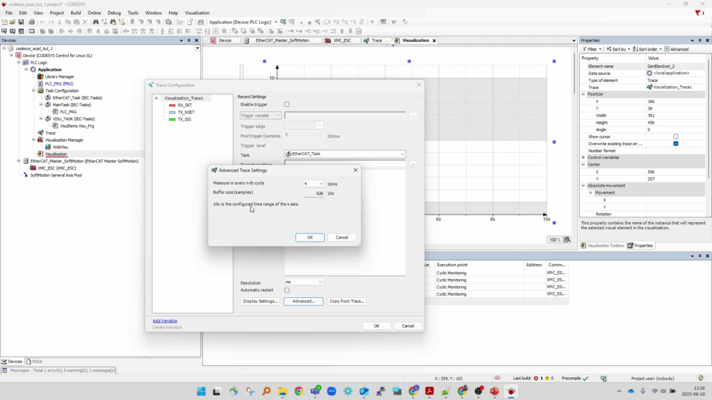
IMPORTANT – The Trace “Widget” is more limited in terms of memory than the Trace “Node” and it may be necessary to update the sample frequency or sample size of the widget.
To do this, select “Advanced” from the Trace Widget’s “Trace Configuration” dialog.
And reduce the sample frequency (ie down-sample it) from every EtherCAT_Task cycle to every 4th cycle (or as required to compile the project without error) as shown:
Save your updated project and re-compile* it.
Toolbar → File → Save Project.
Toolbar → Build → Generate Code
*If there are build errors, it may be necessary to further down-sample the trace widget (Trace Widget → Trace Configuration → Increase “n”)
The project should now have a functional visualization that, once downloaded, can be viewed directly from a display connected to the Soft-PLC.
Download and run updated project on PLC
Download and run the updated project to the Soft-PLC and start it:
Toolbar → Online → Logon → Overwrite OK → Start
Now with the program running you should be able to interact with the Visualization from both the CODESYS IDE and – if your Soft-PLC has a display connected – on the Soft-PLC directly!
Congratulations – your Soft-PLC is now a functioning HMI for an EtherCAT device!