At Simplexity, part of our work is designing embedded motion systems. As embedded motion engineers, we have to know how the smart electronics get placed within the physical structure (“embedded”) and how each component moves relative to each other (“motion”). In this three-part series, I delve into how we describe and model the latter term, motion, which we often take for granted as being quite simple.
In the first of the three posts, I will discuss what we care about with regards to motion. I’ll also walk through an example where it’s appropriate to use simplified motion equations.
What’s at the core of motion analysis?
When we design motion systems, we ask things like:
- – Is the motion stable?
- – How can we make the motion smoother and more elegant?
- – What’s the best way to achieve the desired motion?
To help answer these broader questions, we’re interested in very specific parameters, such as:
- – The orientation of an object at a certain time
- – The velocity of a point on an object
- – Forces and moments applied to the system
If we want to define these parameters and use them to answer our broader questions about the motion, we often enlist the help of trusted kinematic and dynamic models.
Using appropriate models
We must be cautious about the models we choose to use. An oft-quoted engineering saying goes,
“All models are wrong. Some are useful.”
No doubt, the tenet also applies to 3D motion: Some kinematic and dynamic models can be appropriate in one scenario, but they can be insufficient in other scenarios.
For motion, the choice is usually one between universality and simplicity. The universally applicable equations can handle multidirectional 3D rotating and translating bodies, while the simple equations can only handle translation and simple, unidirectional rotation. The simple equations can be appealing, though, because they’re quick and easy. It’s important for engineers of embedded motion systems to know when the simple equations are useful — and when they don’t hold water.
Simple motion analysis
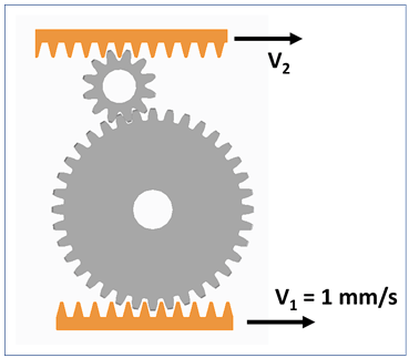
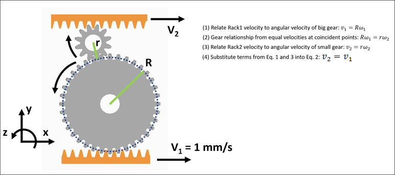
I’ll demonstrate this idea with a simple gear example. In the diagram to the above, the bottom rack is driving the two gears and another rack. Let’s assume the centers of the two gears are fixed, so that the gears are only rotating, and the top rack is moving in the x-direction. If the bottom rack is moving at mm/s, how fast is the top rack moving (assuming no loss in the gears)?
It turns out the equations we need are quite simple. We can easily define angular information in this example:
- The angular velocity
of each gear is equal to the time rate of change of just one angle
. For the larger gear, for example, we can say that its angular velocity is described by
- Each of the gears is rotating about its center of mass.
By essentially treating this system as 2D, we’re safe to use in our analysis (this expression is ubiquitous in references like the Machinery’s Handbook, Wikipedia, and the Engineering ToolBox). Applying the simple
relationship to design our system yields that
. See below in the “Extra Credit” section for a more detailed explanation.
If we want to deal with more complex 3D motion analysis, though, we’ll have to reconsider using these readily available and simple equations.
Please subscribe to Simplexity’s blog for future installments of this series, where I will dive further into those cases.
Extra Credit


