I bet you plug in your phone to a charger every day. (Or if your phone is old like mine, you’re plugging in multiple times a day.) But do you know how much is going on in your USB charging system? Beneath that simple cable and the devices on each end, a complicated protocol ensures that your device can communicate and charge safely and effectively. In this blog, we’ll break down how USB-PD works, from cable detection and power negotiation to role swaps and the importance of cable design—equipping you with a better understanding of what makes this protocol a cornerstone of today’s connected devices.
Key Features
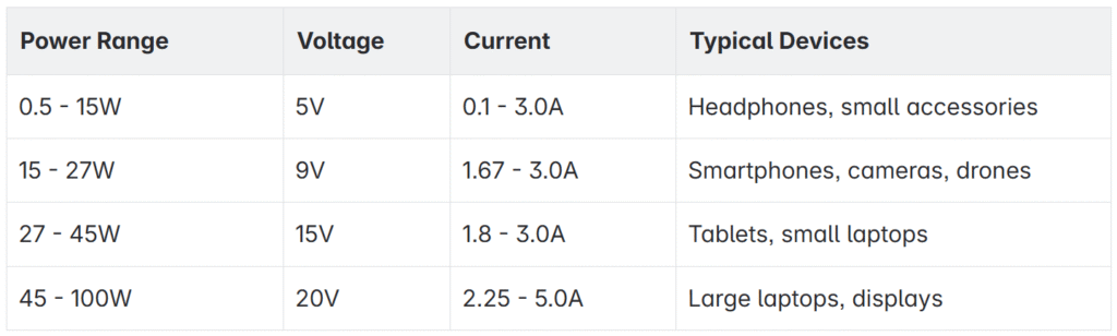
- Higher Power Transfer: USB PD can deliver up to 100 watts of power (240 watts in USB PD 3.1), enough to charge larger devices like laptops.
- Dynamic Power Adjustment: It dynamically adjusts the power flow to suit the connected device’s needs, ensuring efficient and safe charging.
- Bi-Directional Charging: USB PD supports bi-directional charging, meaning it can both send and receive power.
Power Specifications
USB-PD supports various power levels depending on the device’s needs
from androidauthority.com
USB Type-C Pinout and Reversibility
USB-C connectors are 24 pins, as shown in the diagram below. The relevant pins for USB-PD are:
- GND: return path
- VBUS: main system bus (5V, 9V, 15V, 20V)
- CC1/CC2: CC lines used for cable detection, orientation and current advertisement. Note that one of the CC lines may become VCONN (which can power an electronically marked cable)
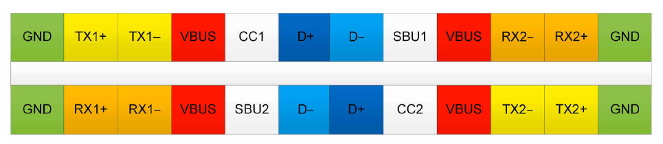 image from
How USB-PD (USB Power Delivery) Works
USB-PD operates through a sophisticated communication system between devices and chargers. We can break it down into 4 phases.
1. Device Detection Phase
- When a device is connected to a USB-PD charger, the system first detects the connection at the hardware level.
- No power is delivered during this initial detection.
2. Communication Phase
- The device and charger establish a dedicated communication channel.
- This channel is separate from the power delivery lines.
- The device sends its identity and capabilities to the charger.
- The charger responds with its available power options.
3. Negotiation Phase
- The device requests its preferred power configuration.
- The charger evaluates the request against its capabilities.
- Both devices agree on the optimal power level.
- If no agreement is reached, they default to a safe power level (5V, 500mA).
4. Power Delivery Phase
- Once negotiation is complete, power delivery begins.
- The charger supplies power at the negotiated voltage and current.
- The device monitors and controls the power reception.
- Power delivery continues until either device requests a change or the connection is broken.
Understanding the CC Line
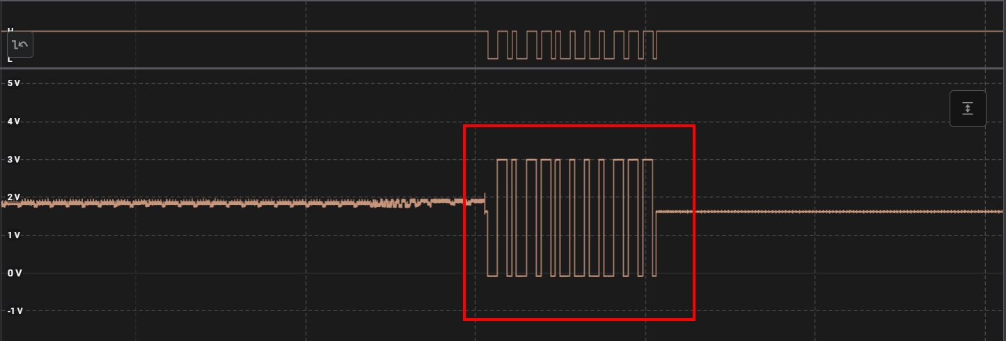
This negotiation happens on the CC line (Configuration Channel), which also serves as a continuous power management signal that indicates the current level after initial negotiation. It uses specific voltage levels to indicate power delivery status:
- Different voltage levels on the CC line represent different power states
- The line remains active during power delivery
- Changes in CC line voltage can trigger immediate power adjustments
Role Negotiation
In USB Power Delivery (USB-PD), role negotiation allows devices to dynamically change their power roles (source/sink) and data roles (downstream/upstream). This is useful for dual-role power (DRP) devices like smartphones, laptops, and docking stations that can act as either a power provider (source) or a power consumer (sink).
Types of Roles in USB-PD
Power Roles
- Source → Provides power.
- Sink → Consumes power.
- Dual-Role Power (DRP) → Can switch between Source and Sink.
Data Roles
- Downstream Facing Port (DFP) → Acts as the host (provides data to a peripheral).
- Upstream Facing Port (UFP) → Acts as the peripheral (receives data from a host).
- Dual-Role Data (DRD) → Can switch between DFP and UFP.
Although source and sink refer to the power roles, and DFP and UFP refer to the data roles, you see source → DFP and sink → UFP used interchangeably in documentation. However, these roles are actually independent.
Role Negotiation Process in USB-PD
Initial Role Determination
1. When two USB-C devices connect, the CC (Configuration Channel) lines determine the initial power and data roles:
- The device with the pull-up resistor (Rp) on CC becomes the Source (provides power).
- The device with the pull-down resistor (Rd) on CC becomes the Sink (consumes power).
- The device that detects an Rd on its CC line acts as DFP (host), while the other becomes UFP (device).
2. If both devices are Dual-Role Power (DRP), a randomized process decides the initial roles.
 DRP role toggling between source and sink (switching between Rp and Rd)
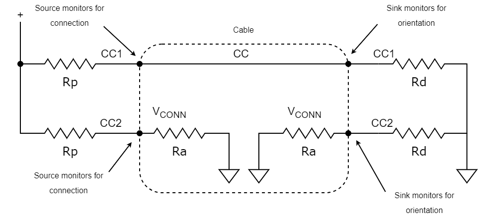 Cable detection with e-marked cable (Adapted from USB Type-C specification v1.2, Figures 4 and 5)
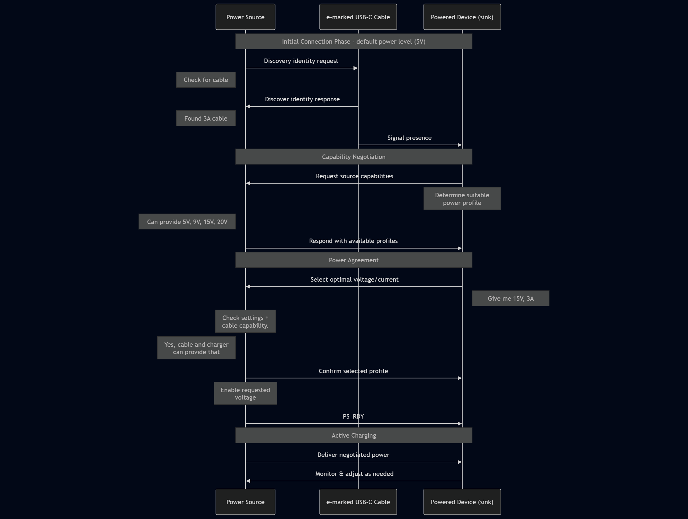
Power Negotiation Process in USB-PD
Below is a sequence diagram overview of part of the power negotiation process
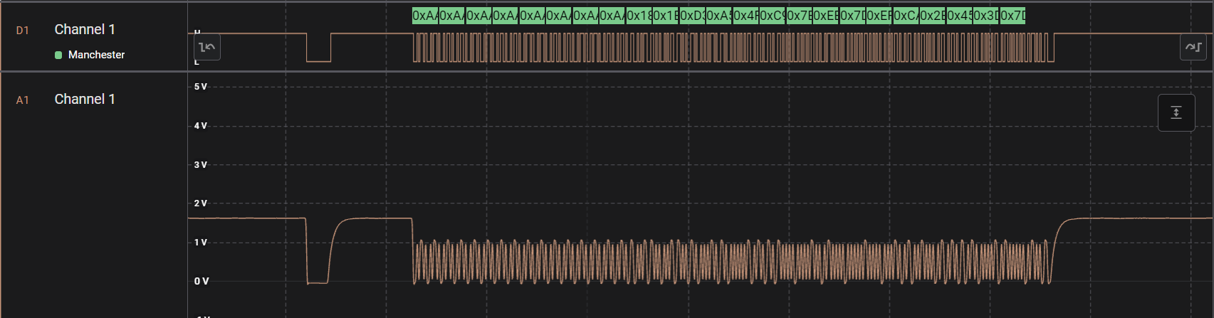
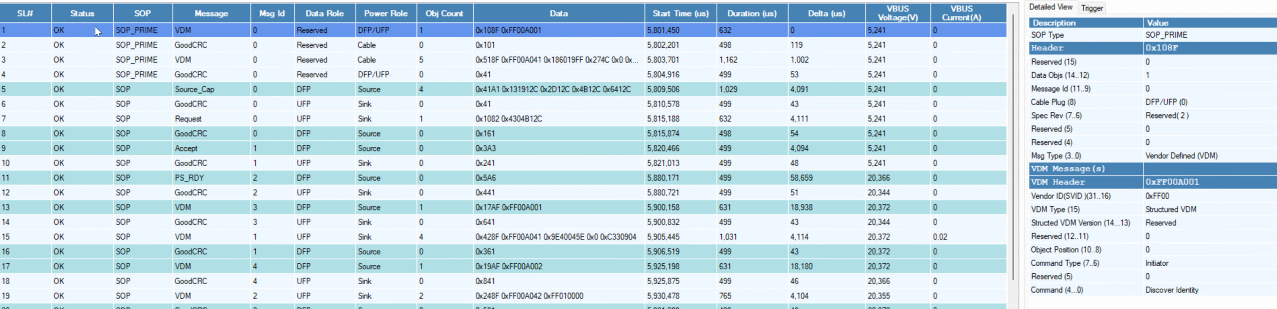
You can download custom analyzers to decode the packet data using a Saleae logic analyzer.
Power Role Swap (PRS)
- A device can request to switch roles using the Power Role Swap (PRS) command.
- The current Source sends a Power Role Swap Request message.
- The current Sink responds with Accept or Reject:
- If Accepted, the devices swap roles.
- If Rejected, the original roles remain.
Example:
-
A phone (Sink) charging from a laptop (Source) can request to become the Source and supply power back to the laptop.
Data Role Swap (DRS)
- The data role can be swapped using the Data Role Swap (DRS) command.
- The current DFP sends a Data Role Swap Request.
- The UFP either Accepts or Rejects the request.
- If accepted, the devices switch roles:
- The DFP becomes UFP (host → device).
- The UFP becomes DFP (device → host).
Example:
- A laptop (DFP) connected to a dock (UFP) may want to switch roles so the dock becomes the DFP and controls peripherals.
VCONN Swap
- If an Electronically Marked Cable Assembly (EMCA) is present, one device must provide VCONN power to the cable’s circuitry.
- A device can send a VCONN Swap request to change which device provides VCONN.
USB Cables
- USB-C unmarked cables: These do not support USB-PD and typically only populate one of the CC lines (which are not technically “CC” lines in USB-C 2.0). This allows the host to detect the orientation of the cable (for D+/D-).
- Electronically Marked (E-Marker) Cables: These cables contain an E-Marker chip that communicates the cable’s capabilities, such as power delivery and data transfer rates.
- Power Transmission: E-Marker cables can support up to 100W of power transmission, ensuring safe and efficient charging for high-power devices.
- Identification: E-Marker cables are essential for devices that require higher power levels, such as laptops and high-performance peripherals.
You can only have 1 e-marked cable per connection, and cable extenders are not supported for two main reasons.
First, USB-C and USB-PD Rely on fixed cable length and integrity
- In USB-C, the CC lines are critical for detecting cable orientation, power negotiation, and communication between the Source and Sink.
- USB-PD expects a direct connection between the devices (or an e-marked cable), and adding an extender disrupts the expected topology.
Second, extenders Break USB-C Connection Logic
Problem 1: CC Line Disruption
- A standard passive USB-C cable only passes one CC line.
- If you add an extension cable, the devices may not detect orientation properly.
- If both CC lines are passed, it could confuse role detection and disrupt negotiation.
Problem 2: E-Marker Detection Fails
- E-marked cables have an internal chip that is queried during power negotiation.
- If an extension cable is added, the Source may fail to detect the e-marker, leading to power limits (e.g., 60W max instead of 100W).
Problem 3: Increased Resistance and Voltage Drop
- USB-PD supports up to 5A at 20V (100W), which requires carefully controlled resistance in the cable.
- An extender increases resistance, causing voltage drops and potential overheating (and therefore fire hazard).
- This is why 5A cables require an e-marker to ensure proper power transmission—and extenders aren’t accounted for in this system.
This can be a challenge for testing or test systems where you need intermediate connections to simply be passed through. However, some test cables are available for compliance testing. ($200 for a single 1-foot cable!) In addition, there are bulkhead connectors with flying leads which pass through all the signals.
Conclusion: USB Power Delivery Explained
USB Power Delivery (USB-PD) has significantly improved the way modern devices charge and communicate power needs—making fast, flexible, and intelligent charging possible over a single USB-C connection. Whether you’re powering a smartphone, laptop, or docking station, USB-PD dynamically negotiates the optimal voltage and current to deliver safe and efficient energy transfer. The nuances of cable integrity, role negotiation, and the communication protocol can be a challenge during development, but this complexity is what allows us to power such a wide variety of devices. Using USB-PD allows us to use the same cables for many different devices, reducing electronic waste and saving money for consumers.