The Three Steps of Tolerance Analysis
By: Neil Foxman, Senior Systems Engineer, San Diego office
Transforming your mechanical CAD designs into real and tangible parts is one of the most rewarding feelings as an engineer. However, a lot of things can go wrong during this transition. One of the most common and most overlooked problems are tolerances. Have you ever tried mounting your TV on your wall, but the holes don’t line up perfectly? Or do you have to jiggle your keys every time you open the front door? These issues occur because of poorly controlled tolerances.
Controlling tolerances is an important part of any designer’s responsibility. In applications like optics, precision motion, drive trains, and plastic enclosures, tolerances become extremely important, and the overall design is essentially dictated by tolerance requirements. In this article, we will walk through step-by-step examples and illuminate the path to good tolerancing in your designs.
| Download a copy of our Whitepaper: |
Download a copy of our Tolerance Analysis Template: |
 |
 |
TOLERANCES
Mechanical designs and mechanical drawings use a nominal dimension to describe a width, height, depth, diameter, or radius on a part so that the part can be built. A tolerance is associated with each dimension because as designers, we know that the part will never be 100% atomic-level accurate, but instead can be “close enough” within some range of the nominal dimension.
Tolerances are typically specified using a symmetric ± tolerance zone. This means that when a part is manufactured, the actual dimension can be some distance more or less than the nominal dimension. Imagine you are designing a microscope fixture. The microscope bottom needs to be 6 mm away from the slide, and the focal range is 0.5 mm wide, so the dimension between the microscope and the slide should be 6 ± 0.25 mm. The tolerance of this dimension is the “± 0.25 mm” part which means that the actual measured distance after manufacturing can be 5.75 mm to 6.25 mm. You would likely find this dimension on a list of design requirements determined before design even begins or on the microscope data sheet.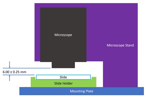
Often tolerances specified in parts are driven by the manufacturing methods available. A larger tolerance zone allows the manufacturer to be less strict in how the design is made, and so the design is said to have a looser tolerance. On the other hand, a tighter tolerance dimension is one that is difficult to achieve because the tolerance zone is so small.
A good mechanical drawing is also likely to have more elements than just dimensions and tolerances. In addition to revision tables, notes, and part numbers, drawings also commonly have hole callouts, fitment callouts, and Geometric Dimensioning and Tolerancing (GD&T) symbols to help the manufacturer understand and produce your design. Although these elements are often important in tolerancing, they are beyond the scope of this article.
A TOLERANCE “STACK”
Even if the production methods allow you to design tight tolerances on a single part, you need to consider the tolerances of all the parts around it to make sure that the overall system functions correctly.
Let’s revisit the example of the microscope fixture. Our microscope needs to be held at a specific height above a slide, so we plan to design a microscope stand, a slide holder, and a mounting plate for the parts to be mounted on. We know that the microscope needs to be held 6 ± 0.25 mm away from the top surface of the slide, and we plan to machine the parts using a CNC milling machine which has an accuracy of ± 0.2 mm. The machining tolerance zone is smaller than the required tolerance zone, so no problem, right?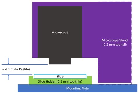
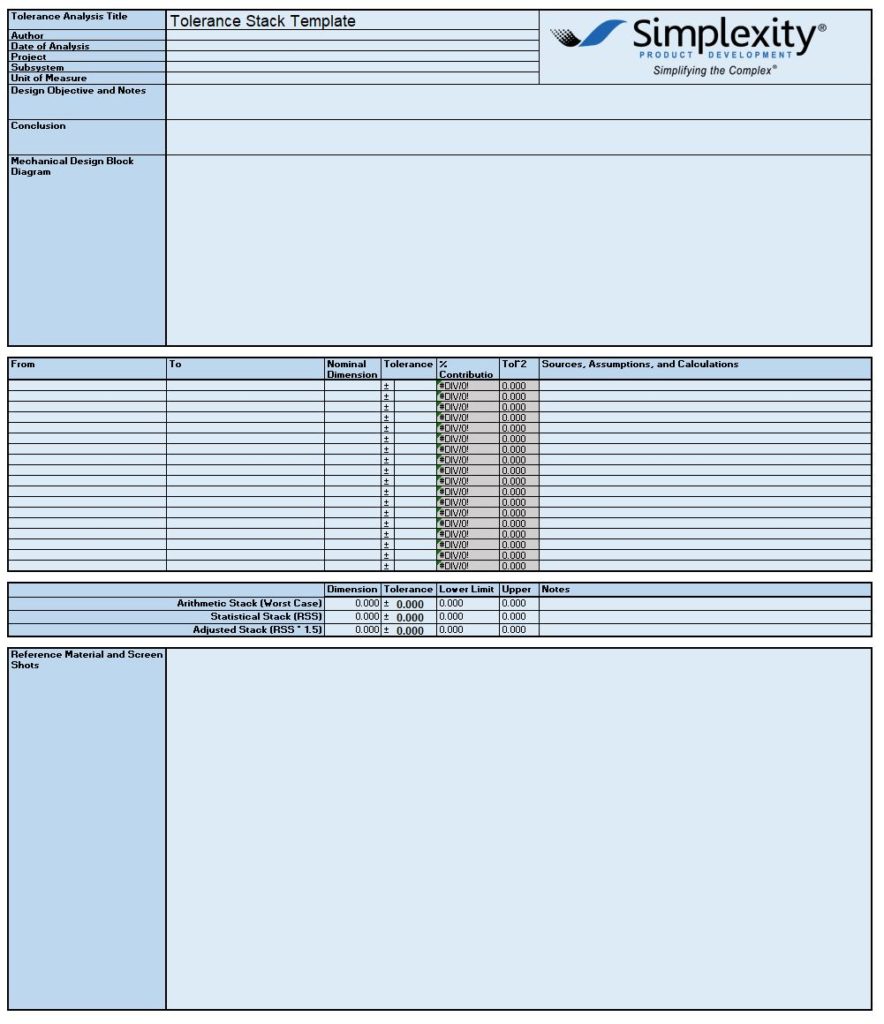
Well, actually no. Each of the parts may be 0.2 mm away from what we want. So, if the microscope stand is 0.2 mm taller after machining, and if the slide holder comes out 0.2 mm thinner, then the slide would actually be 0.4 mm away from the nominal 6.0 mm, causing the image to be out of focus. In a case like this, you would need to do a tolerance analysis of the tolerance stack-up to make sure the design will work. A tolerance analysis looks at all the relevant tolerances in a system and adds them so that we can improve the design to meet a certain design requirement. A tolerance stack-up analysis is usually done on a spreadsheet. Feel free to use this Tolerance Analysis Template to get started. We will be using this template later in this article to walk through the analysis.
In a product design, a designer would usually conduct two tolerance analyses. An Architecture Tolerance Analysis is conducted in the early design stages. In product design, “architecture” generally refers to a high-level design where the details aren’t worked out yet, but the designer can begin to get a sense of what components need to be made or purchased. At Simplexity, this analysis would be conducted during Phase 2A. For more information on our Product Development Process, you can refer to: https://www.simplexitypd.com/resources/product–development–process/.
The second tolerance analysis, or Detail Tolerance Analysis, updates the previous stack-up and confirms the finalized design before release. This update usually occurs during Phase 2B. However, tolerance analyses are typically iterative, and you may also want to update your analysis whenever the manufacturer, material, or architecture changes.
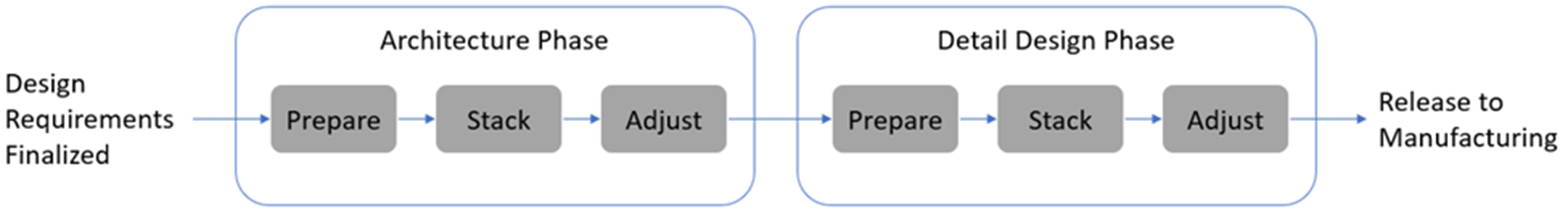
Each time a tolerance analysis is conducted it can generally be split into three steps: Prepare, Stack, and Adjust (or PSA). In this article we will walk through these steps for the Architecture Tolerance Analysis and the Detail Tolerance Analysis.
You don’t need a tolerance analysis for every measurement in the system, so it is up to your design requirements and engineering intuition to gauge when an analysis is needed. As a general Rule of Thumb, you should conduct a tolerance analysis when:
- Two or more parts need to be aligned precisely to ensure function of the assembly, or
- One or more parts are using “looser tolerance” manufacturing methods.
ARCHITECTURE TOLERANCE ANALYSIS
Here we will walk through the Architecture Tolerance Analysis using the Prepare, Stack, Adjust method. This analysis helps you catch any major design issues before spending too much time on detail design. Before starting the analysis, you should already have a rough idea of the part quantities, the manufacturing methods available, and which parts are important. However, if your design is already too detailed with fastening features and drawings, be prepared for some design changes!
Step 1A: Prepare – Rough Block Diagram
Because tolerance analyses are usually done before detailed design is complete, I highly recommend making a rough block diagram of your system. Basic diagrams clarify important interfaces and dimensions before the design is detailed, and they serve as an important tool for communicating your findings at design reviews.
It’s best to put the block diagram right on the tolerance stack spreadsheet, but you can also make blocks in PowerPoint or draw.io. The diagram should only give a general sense of the relevant parts, and not be too detailed.
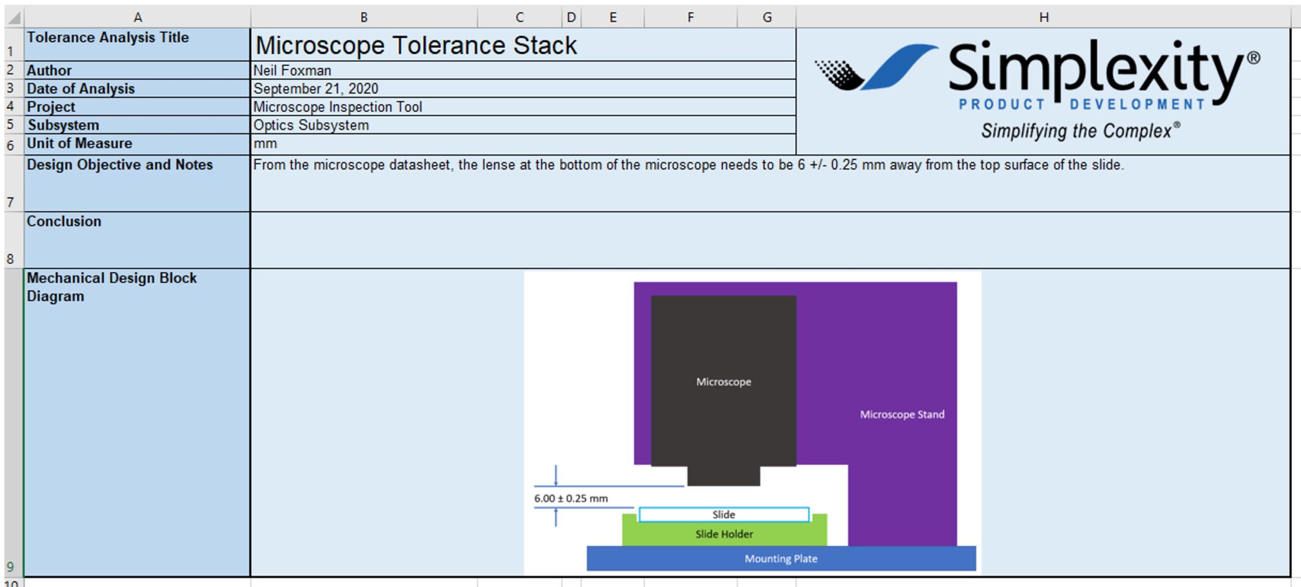
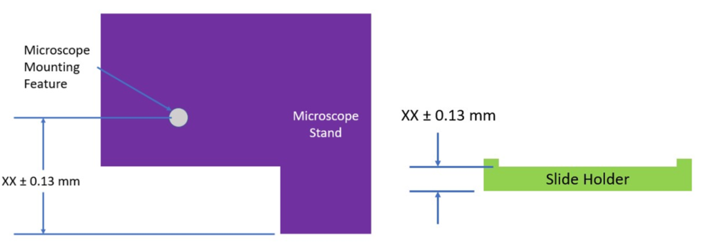
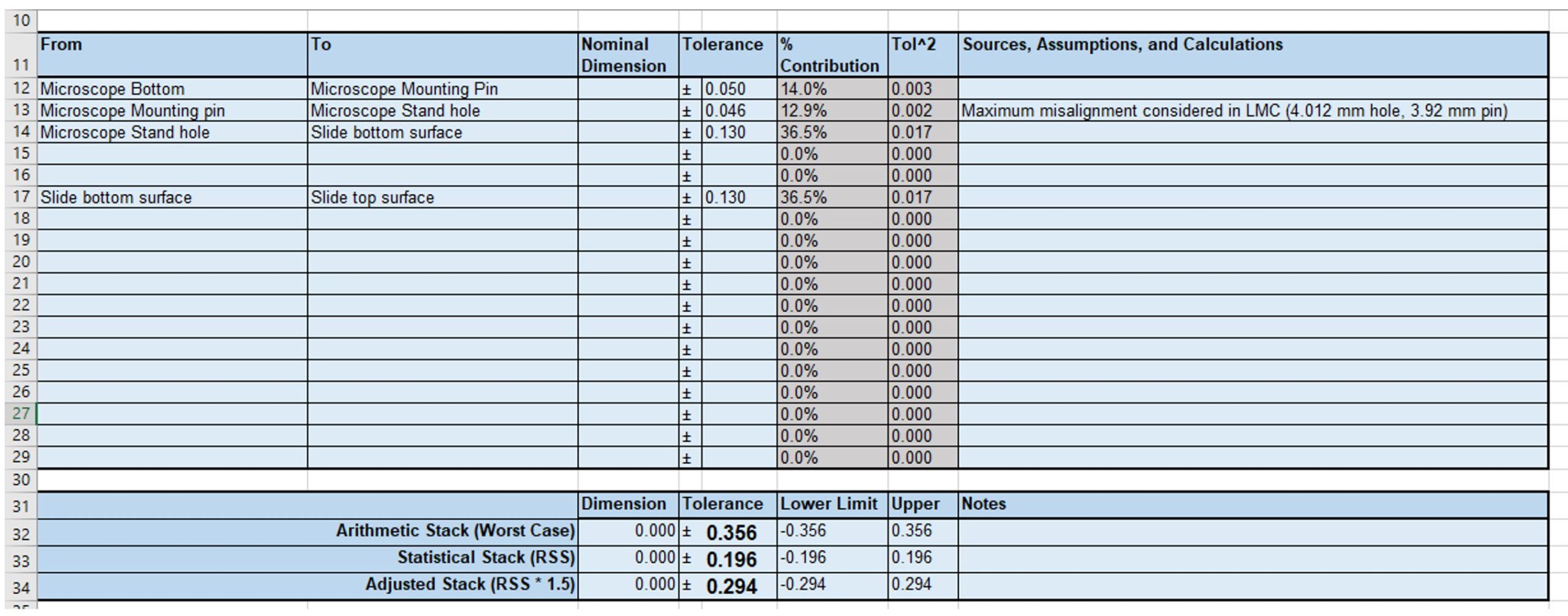
Returning to our microscope fixture mentioned earlier, the block diagram for this fixture can be put directly on the tolerance analysis spreadsheet as shown below. Fill out the document header with information such as the project, designer, and the goals of this tolerance study.
Step 1B: Prepare – Find the Manufacturing Tolerances
Now that you have a better sense of the parts used in the stack, you can start finding each part’s manufacturing tolerances. We may end up specifying different tolerances later, but the goal is to get a rough-order-of-magnitude or “ROM” estimation of each part’s tolerances at this stage to catch if your design is way off and needs larger architectural or manufacturing changes.
I would recommend looking for tolerances on rapid prototyping manufacturer websites. Most prototyping manufacturers automate their process, so they are more likely to post tolerance information online instead of assigning someone to review each customer drawing. For instance, we commonly use Protolabs for machining prototype parts, and they have good design guides with tolerances for CNC milled parts, CNC turned parts, and sheet metal parts.
If you are using off-the-shelf or “OTS” parts, look for part datasheets or drawings that will show you the important dimensions and tolerances.
Let’s now find the relevant tolerances for our microscope fixture example. As we’re preparing our analysis, we will need some tolerance estimates for all parts that determine the vertical distance between the microscope and the slide. So according to our diagram we need tolerances for the microscope, microscope stand, slide holder, and slide. We don’t need to consider the tolerance for the mounting plate as its vertical dimension doesn’t impact the distance between the slide and microscope i.e. if the mounting plate is too thick or too thin, the microscope height above the slide still remains the same.
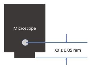
We will plan to mount the microscope on the microscope stand using some alignment features. Let’s say our microscope has a datasheet that claims the tolerance between the bottom of the microscope and a mounting pin is 0.05 mm. Note that we don’t yet care what the actual dimension is, just the tolerance zone.
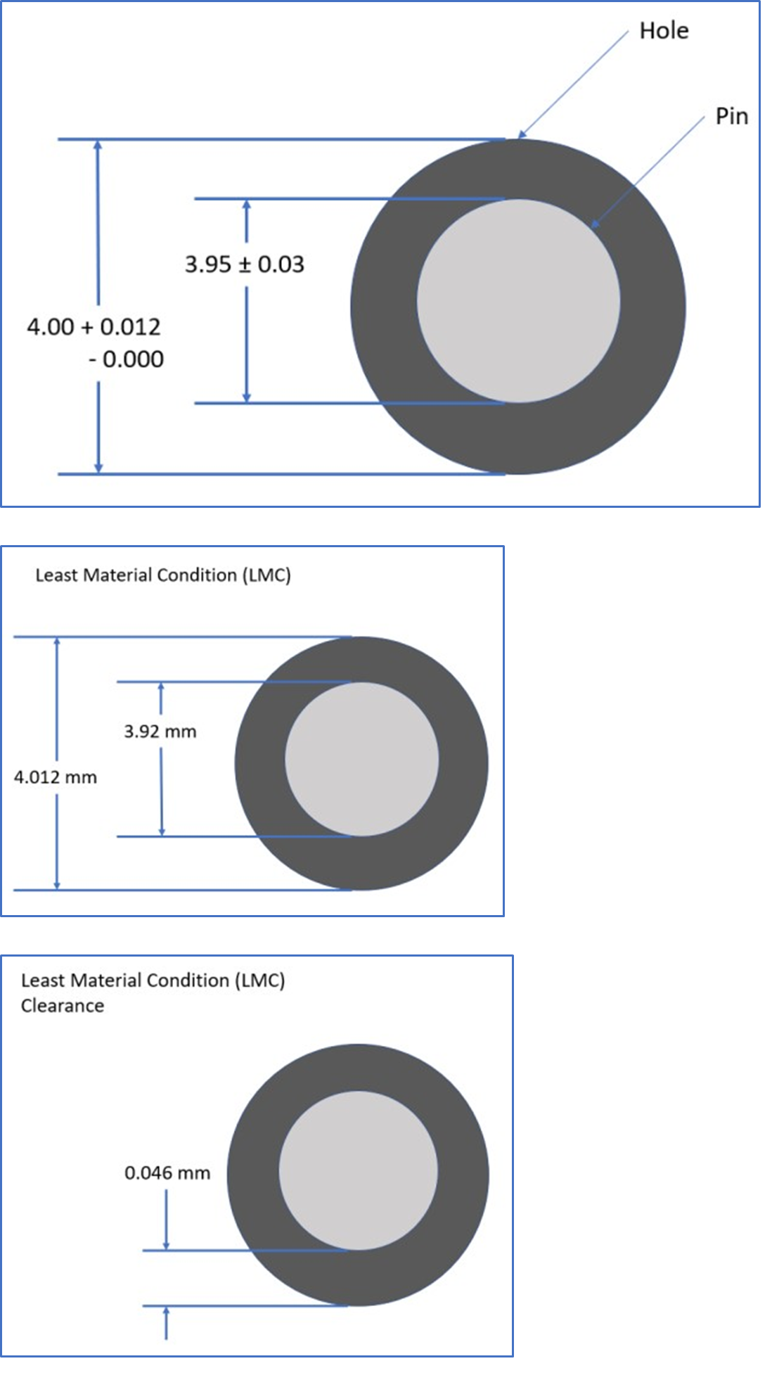
Let’s plan to fit the mounting pin on the microscope into a clearance hole on the microscope stand. Looking again at the microscope datasheet, we see that the mounting pin has a diameter of 3.95 ± 0.03 mm. A common ISO 286 tolerance zone for a hole is H7 which has an asymmetric 0.012 mm tolerance zone (4.000 +0.012, -0.000 mm). For other hole/shaft fits, you can use the tool on Engineer’s Edge. This tolerance zone is asymmetric, but we will revisit this fit in the stack phase to see how it can be used.
Next, we can assume that the microscope stand, and slide holder are made using a CNC milling machine, so we would like to find some tolerances for these parts. Looking at our manufacturer website, they claim that their usual machining tolerance is 0.005” (0.13 mm). Again, we don’t need the dimensions as these parts haven’t been designed yet, we just need to know that if we ask the manufacturer to make two features some distance from each other, they can be accurately machined within 0.13 mm.
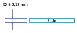
Finally, the slide thickness will have its own tolerance. Early in the design process, there is often missing information. In this case, we don’t yet know if we want the microscope fixture to support a number of slides or just one specific brand, so instead we can do a Google search for glass slide manufacturers and take a rough guess at the slide thickness tolerance assuming we will revisit it later. In this case let’s assume we found a slide manufacturer that quotes their thickness to be within 0.13 mm.
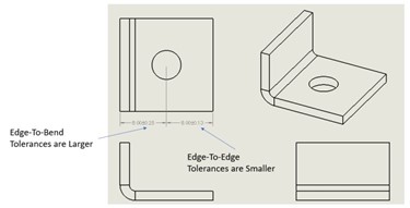
Although the microscope fixture uses generally simple part geometries, it’s worth noting that you should try to visualize how each part will be made, as some production methods can have vastly different tolerances depending on the part orientation. For instance, sheet metal tolerances between two edges on the same plane can have much tighter tolerances than the dimension between an edge and a bend as shown below. 3D printed parts may also be sensitive to the build orientation. In general, machined parts have tighter tolerances when the part is only held in one orientation, but tolerances increase between features when the part is flipped or moved within the machine. For all these manufacturing methods, smaller dimensions may also have tighter tolerances than larger dimensions.
If you find any tables or web pages you find useful, you may want to copy that information into the bottom section of the spreadsheet for faster analysis and review.
Step 2: Stack – Fill out the Tolerance Stack
Now that we have an idea of the relevant part tolerances, it’s time to create our Tolerance Stack using the template provided. Let’s enter each tolerance found earlier into the spreadsheet. It helps if there is a logical order to the tolerances entered in the spreadsheet, so we will look at each dimension along the way from the bottom of the microscope to the top of the slide.
We first enter the tolerance from the microscope bottom to the microscope mounting pin. Enter the description of the relevant features in the From and To columns and the numerical tolerance on the top line. Ignore the nominal dimension column for this study, and don’t change the formulas in the gray columns because these will update automatically. The second section in your tolerance stack should now look like this:
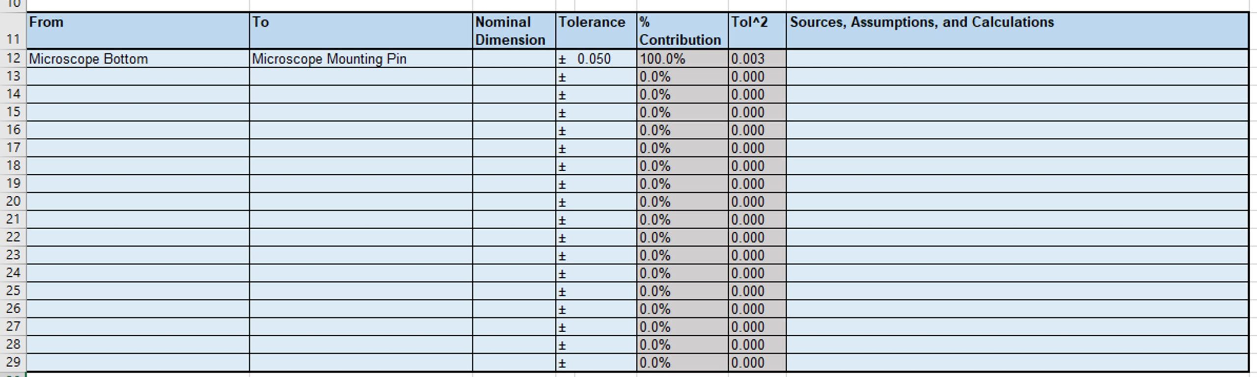
It’s a good idea to be verbose with what dimension you are referring to in the From and To columns so that your thinking can be more clearly communicated to a reviewer and to give yourself a reminder during design.
Next, some care needs to be taken when considering the fitment between the microscope mounting pin and the hole in the microscope holder. Because this is a clearance hole, there can be some misalignment, and we need to consider the worst-case condition for our tolerance stack. In this case, we get a maximum misalignment of the microscope to the microscope holder in the Least Material Condition where the hole is at 4.012 mm and the pin is at 3.92 mm. This means that there is a possible misalignment of 0.046 mm as shown below.
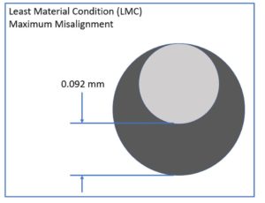
To capture this possible misalignment in our tolerance stack, we need to add another line showing this position tolerance possibly including some notes on how this tolerance was achieved.
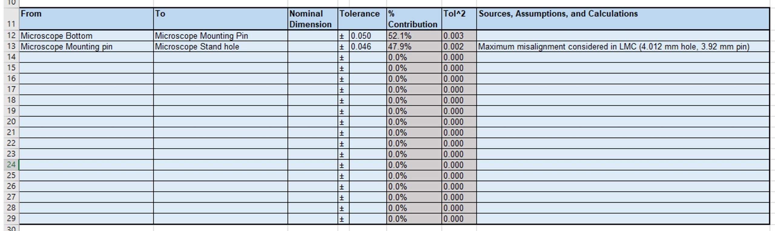
The rest of the tolerances are machining tolerances between features on the microscope holder, slide holder, and slide. We can enter that information into the spreadsheet as shown. Notice how each dimension is fully described in order from the microscope to the slide.
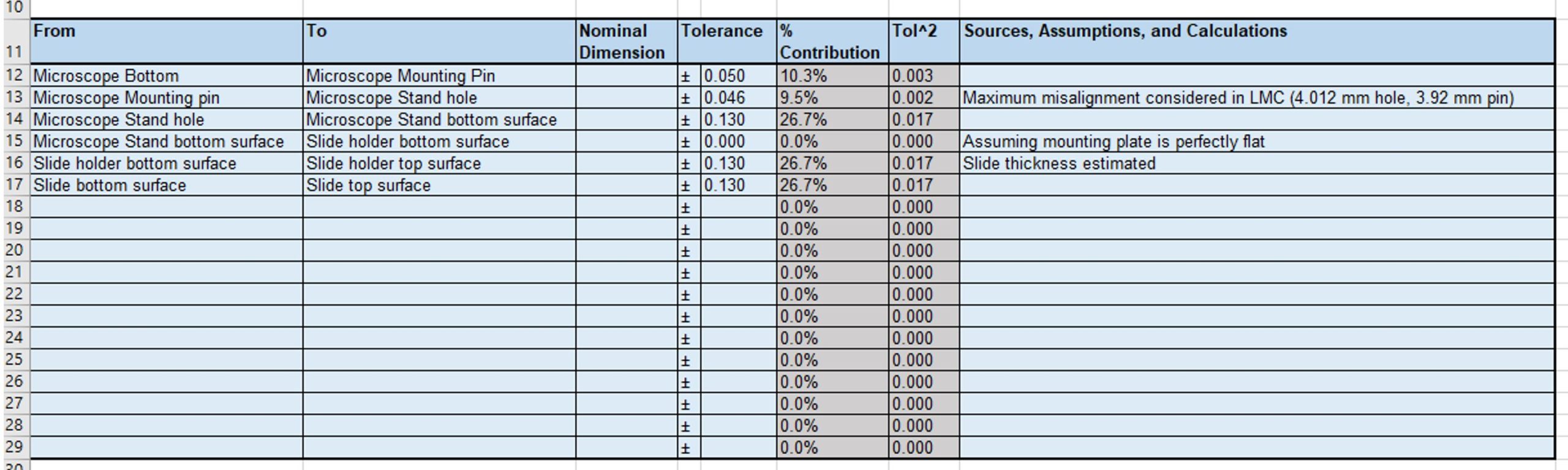
Finally, you can see the total tolerance of the stack in the third section of the spreadsheet.

For now, the focus of this exercise is the top line of this section: Arithmetic Stack (Worst Case). The value in the tolerance column represents the sum of all the tolerances in the stack. It looks like we will currently not be able to meet the requirements because our total possible misalignment is ± 0.486 mm but our requirements state that we need to be within ± 0.25 mm. We now need to make some fixes to the architecture which we will do in the next step, Adjust.
Step 3: Adjust – Modify Tolerances to Meet Requirements
For tight tolerance applications, you will commonly find yourself adjusting the tolerance stack or the mechanical architecture to meet the requirements. If the designed tolerances are too loose, you can try some of the following techniques:
- Reduce the number of parts in the stack
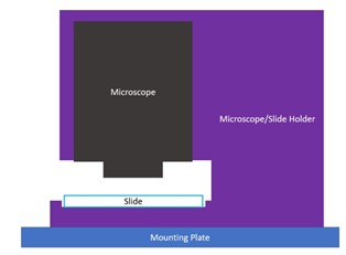
If you can remove a part from the assembly, you are also reducing the overall tolerance stack. Design the system so that only one part has the critical dimensions. In this case I may consider eliminating the slide holder altogether and make one part that holds both the slide and the microscope. This would mean the dimension between the microscope alignment hole and the slide bottom surface can be a single manufacturing tolerance of 0.13 mm.
I can then adjust my tolerance stack to look like the one shown below.
The tolerance has improved (gotten smaller), but still doesn’t meet the requirement of ± 0.25 mm
- Use tighter tolerances on the parts
It may seem overly simplistic, but you may find that you can achieve better tolerances than you first assumed by looking at alternative vendors or manufacturing methods. If you were originally planning on using 3D printed plastic, consider if the critical alignment features could be replaced by a sheet metal bracket or machined part. Also, you can look for vendors with tighter tolerance specifications as the tolerances are commonly dependent on what tools they have in the shop. Instead of a clearance hole, we can investigate using a press-fit hole to remove the possible misalignment tolerance.
- Consider using or modifying off-the-shelf precision parts
Modifying off-the-shelf parts is also a good cost-cutting method. Instead of designing a custom shaft with really tight tolerances, you may instead choose to machine your features into a stock shaft that you purchase with tight tolerances. For the microscope holder, I would ask the microscope vendor if they supply any mounting brackets that hold tight tolerances or a bracket that can hold the slide to a controlled surface.
- Introduce compliance and float into the system, and perform critical alignment during operation
This concept introduces more complexity to your design, but it is likely to significantly reduce the total tolerance stack of your system. Instead of fixing each part at a single position and making the machining tolerances tight for all the parts, consider allowing most of the parts to have loose tolerances or move in space. Then introduce an engagement step or clamping step where the critical parts are aligned with a single part.
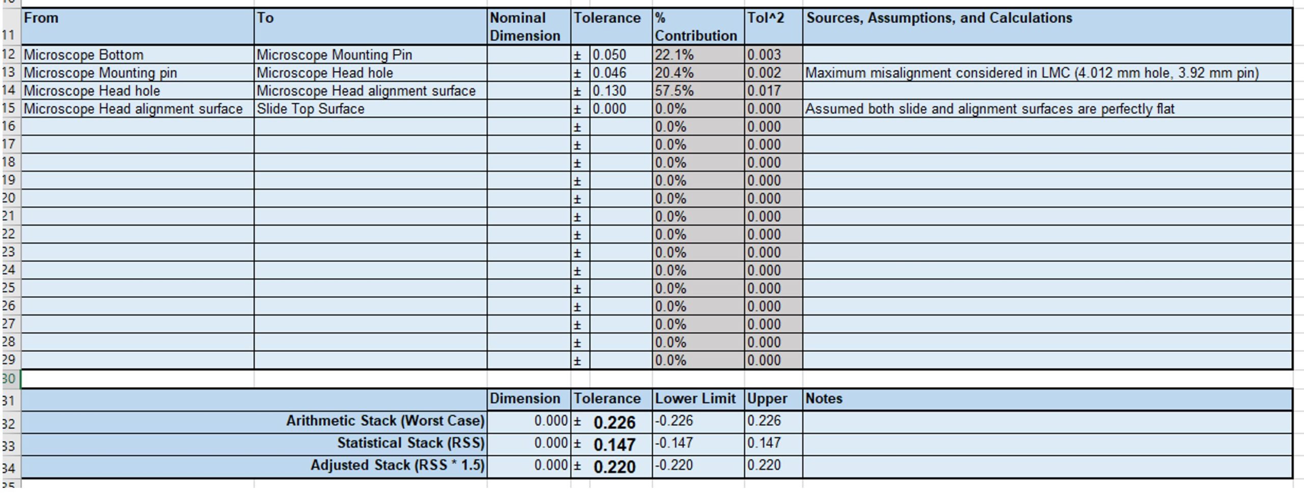
In our microscope holder example, this could be a custom designed Microscope Head that is spring loaded against the top surface of the slide. In this case we don’t care as much about the tolerances of the other parts, and only need to control the dimension between the Microscope mount features and the slide surface. Our system and tolerance stack would then look like:
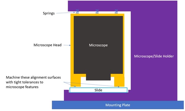
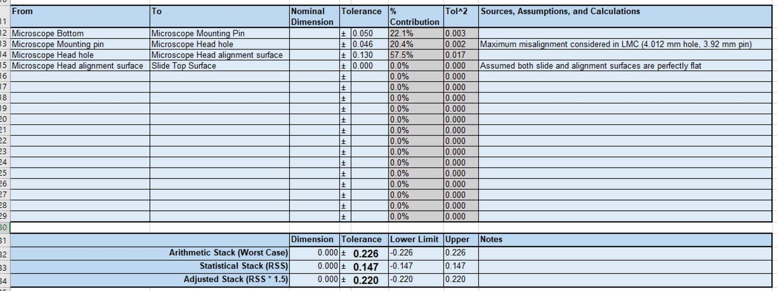
We are now within our target tolerance zone! This architecture should work for our design, but it’s worth noting that the complexity has increased: you now have to design the spring mechanism and investigate if the additional forces on the slide cause it to break or warp.
5. Revisit the tolerance requirements
Satisfying a requirement may be as easy as changing the requirement itself. Communicating with other team members will likely help you identify how the requirement was originally specified, how strict the requirement is, and if the requirement could be satisfied in an alternative design. Early requirements are often rough guesses, and it helps to quantify how time and costs can be reduced by relaxing a given requirement.
6. Use the Statistical Stack, and Adjusted Statistical Stack
So far, we have been using the Arithmetic Stack (Worst Case) to determine if the design is feasible. However, it may not be cost effective to design using this metric, and you may choose to instead use the results for the Statistical Stack (RSS) or Adjusted Stack (RSS * 1.5) in the lower section. We will discuss these analyses in more detail later in this article.
Sometimes the tolerances are just too tight to design around, and you need to start looking at more expensive operations. Some additional options are listed below.
- Introduce additional design controls
Adding GD&T tolerance callouts to your drawing adds further control to your design if you know how to use them properly. More design controls generally increase the cost of your parts because they require slower machining speeds, create additional machining steps (like lapping), or introduce inspection steps after manufacturing. However, there are specific callouts for flatness, parallelism, and position that may be able to give minor benefits.
- Alignment/calibration in production
Similar to designing compliance into the system, you can also design the parts with loose tolerances and include an alignment step during production. In general, this means you would design clearance between the critical parts, and then use a single precision alignment fixture to make sure that they are aligned properly before tightening and fastening them into place. Note that this will increase the overall product cost because not only are you designing an additional alignment fixture, but you are also adding labor to the final assembly. This also potentially makes repairs more difficult if any modification requires a recalibration as well.
3. Use Precision Manufacturing methods
There are some specialized tools that allow you to make very precise parts at high cost. For example, Electrical Discharge Machining or EDM will likely be the most precise manufacturing methods available for a mechanical design, but it incurs a significant cost and potential impact to schedule. Some dimensions can be held to an astounding ± 0.001 mm, and I would recommend looking for some YouTube videos like this one to gawk at the capabilities. However outside of hyper-precision applications, if you need to use EDM you are likely overlooking some other easier alternatives.
If you need to make architecture or manufacturing changes, repeat the process: Prepare and research what the updates entail, add or remove parts in the Stack, and Adjust the design until the tolerances are reasonable and you can proceed with more detailed design.
DETAIL TOLERANCES ANALYSIS
The Detail Tolerance Analysis is focused on verifying your design tolerances before release. In this stage, the detail design of your system should be almost done, and you revisit your original estimates to get more accurate tolerances. It may help if you have mechanical drawings while filling out the Detail Tolerance Analysis.
To continue our previous example, let’s assume that we were able to bring our tolerances within our requirements using the compliant spring concept for our design.
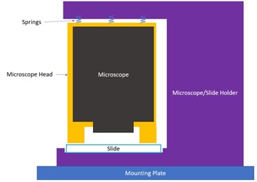
Our tolerance stack upon entering the Detail Tolerance Analysis would look like the one shown below.
Step 1: Prepare – Contact the Vendors
In the Architecture Tolerance Analysis, we estimated some of the tolerances using information from similar vendors or similar manufacturing processes. Now is the time to send the drawings to vendors to confirm that the tolerances you specify are appropriate.
For injection molded parts and cast metal parts, a vendor may provide you with a Design for Manufacturability (DFM) document that highlights issues with your design. Even if the manufacturer had previously quoted certain tolerances, the tolerances may be adjusted (for better or worse) after a rigorous DFM that looks at thin features or possible warping during manufacturing.
Step 2A: Stack – Update Parts
Add any new parts that were not present in the first analysis and might affect the overall tolerance. Some components that are often forgotten are shims, washers, gaskets, and thermal interface material.
Some parts like PCB’s have percentage tolerance zones. In these cases, feel free to put their thickness in the Nominal Dimension column and put a percentage formula in the Tolerance column.
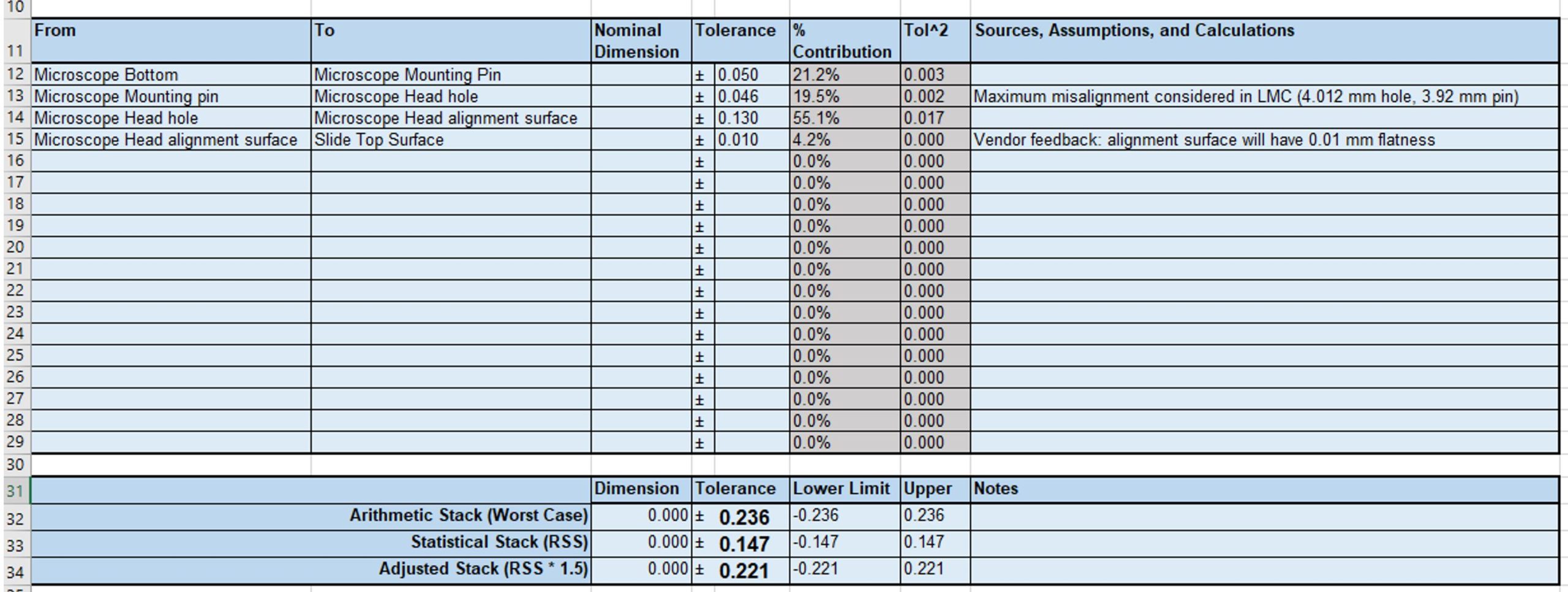
In the example case of the microscope holder, let’s assume that the vendor suggests we need to call out a flatness tolerance on the alignment surfaces of the microscope head at ± 0.01 mm because of the surface size.
In that case we can update the tolerance stack to the one shown below.
Step 2B: Stack – Determining Gap or Interference (Optional)
Using a coordinate system and adding dimensions helps in cases where you are designing the parts to a specified gap or a specified interference. With our microscope fixture, we want a nominal gap of 6 mm, so we can verify this by including the dimensions in the Nominal Dimension column as shown below. In this case, I am defining upwards dimensions as positive and downwards dimensions as negative.
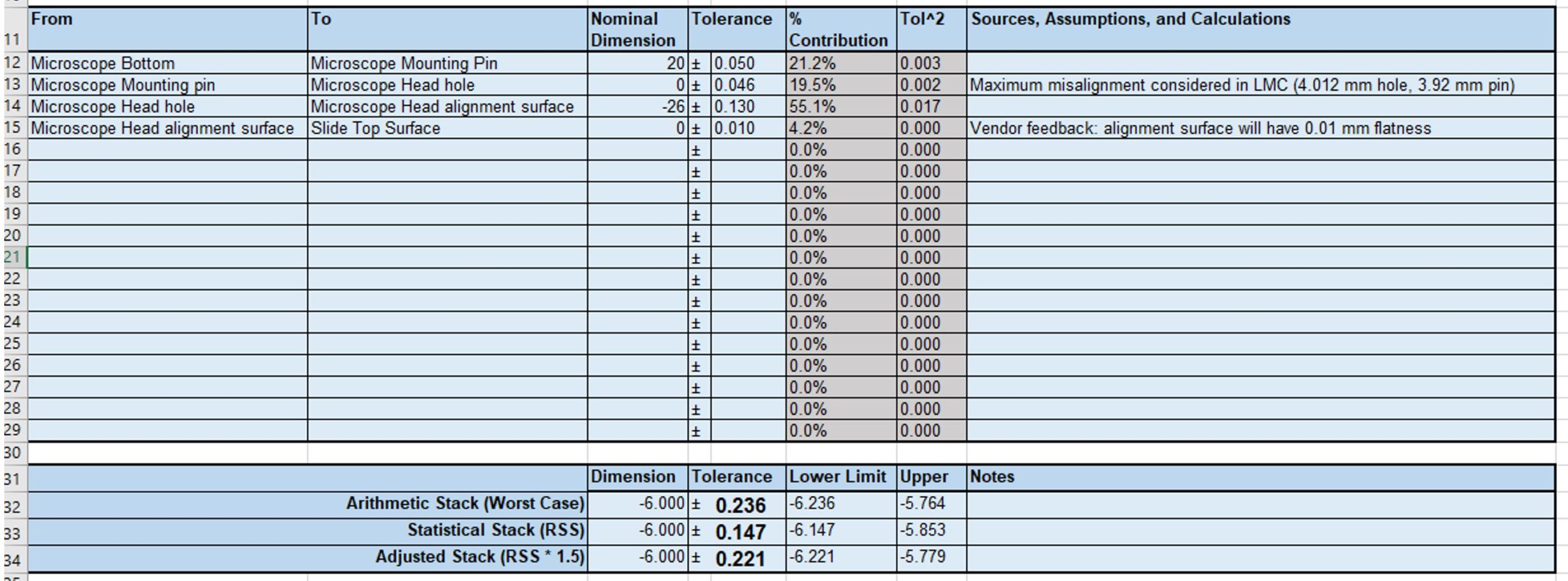
In the lower section, this allows us to see that the Arithmetic Stack from the Microscope Bottom to the Slide Top Surface is between 5.764 and 6.236 mm in the negative direction.
Tolerance stacks should generally list the tolerances along one dimension (X, Y, or Z). However, some engineering intuition should be used to determine if the tolerances are reasonable for curved, drafted, or diagonal tolerance stacks. In more complicated cases, I would recommend using conservative estimates or inspecting some test parts to gain more confidence that your tolerance analysis is reasonable.
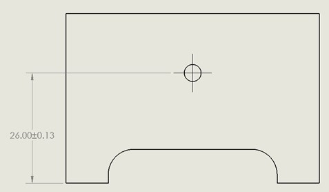
Step 3: Adjust – Update the Tolerances on the Mechanical Drawing
A mechanical drawing is a communication tool that allows you to specify the important tolerances of your design. If a dimension is in your tolerance analysis, that exact dimension should also be called out in the drawing.
Here, I have dimensioned the distance between the Microscope Head Hole and the Alignment Surface correctly according to the tolerance stack.
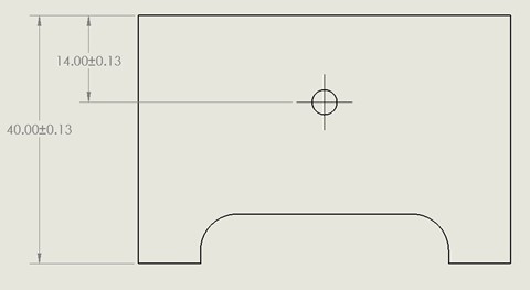
In the image below, the dimension has been called out incorrectly because now there are two ± 0.013 mm tolerances between the Microscope Head Hole and the Alignment Surface.
Once your drawings and tolerance analysis spreadsheet are aligned, your tolerance analysis is completed, and you are ready for release!
NOTES ON STATISTICAL APPROACH
Stated manufacturing tolerances are commonly a statistical measurement and not a perfect limit to the parts you will get. This is an important concept because there is no “perfect” tolerance stack and there will always be a slight chance that the produced part dimensions will be too big or too small.
However, that also means that even if your worst-case tolerance stack does not meet your requirement, the chance of every part in the stack coming in at the worst case condition can be very unlikely. Even if your tolerances are looser than the requirements, it may be more cost effective to leave the design as-is. This decision depends on the likelihood of poor tolerances and the manufacturing cost required to improve them.
Let’s look at two different hypothetical manufacturing options for making 100 parts. You get two quotes for your part, you can either use a precise wire EDM tool at $10 per part, or a CNC mill at $5 a part. With EDM, the vendor assures you there is almost zero risk of making a bad part, whereas with the CNC mill the risk of a bad part is higher (say 5%). To make 100 good parts, you could expect to pay 100 x $10 = $1000 for the EDM parts, but only 105 x $5 = $525 (with 5 parts coming in out of tolerance). This illustrates the importance of considering statistics along with your tolerance stacks.
In statistical terms, if you assume that all the tolerances in the spreadsheet actually represent 3 standard deviations away from the nominal value, then the total tolerance (using 3 standard deviations) is calculated using a “Root Sum of Squares” or RSS value. This RSS value is included at the bottom of the tolerance analysis template.
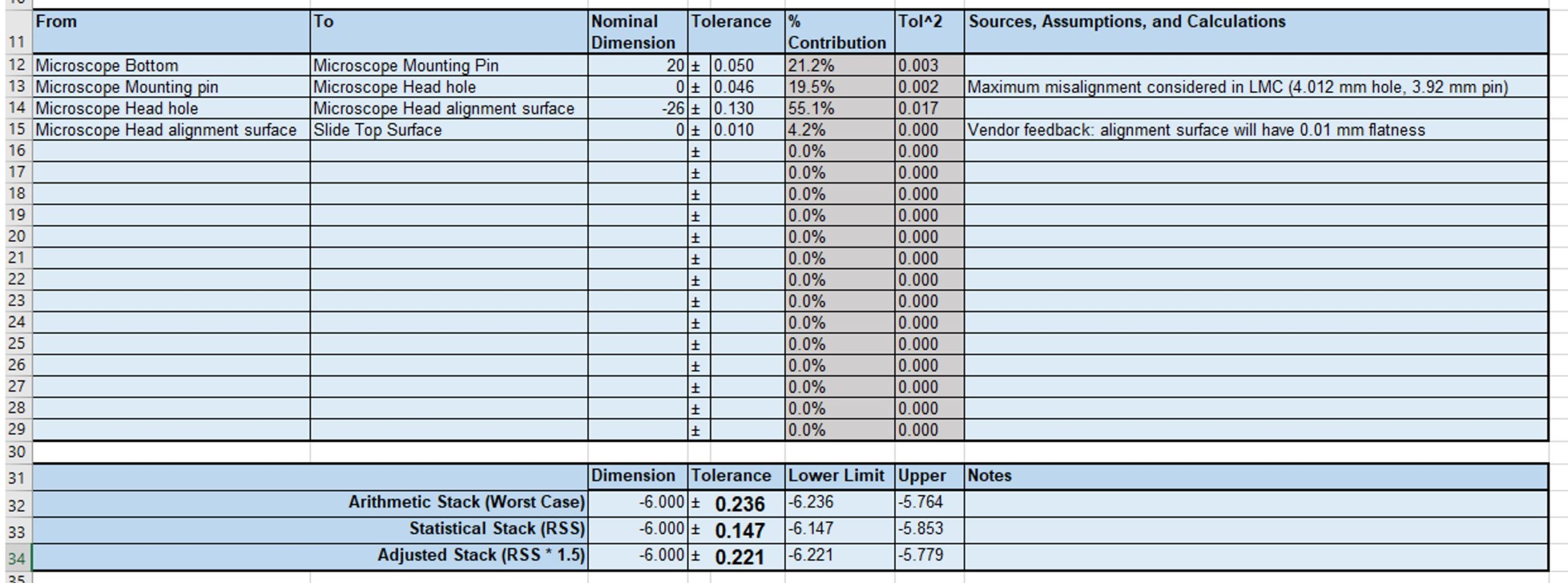
In other words, if 99.7% of the Microscopes and 99.7% of the Microscope Heads have tolerances within the ranges listed in the table, then 99.7% of the assembled systems will be within the ± 0.147 mm tolerance zone which is smaller than the “worst-case” tolerance zone of ± 0.236 mm. I won’t go into the proof here, but the reasoning is that when adding two random variables, the variances also add. This article is a good refresher on these concepts for those familiar with Statistics: http://www.stat.yale.edu/Courses/1997–98/101/rvmnvar.htm
You may notice that the spreadsheet also includes a value for the RSS*1.5 tolerance zone. The 1.5 is a safety factor used to make the result a little more conservative. This 1.5 value has no mathematical interpretation, but it is commonly used in quality control. To reduce risk, you can edit the formula within the spreadsheet and increase the safety factor.
CONCLUSION
Our walkthrough of both the Architecture Tolerance Analysis and the Detail Tolerance Analysis can help serve as a guide when you look at the tolerances of your own designs.
Tolerance analyses don’t just apply to mechanical parts; in the engineering world, most measurements are approximate and knowing the tolerances of the components you buy can help you better gauge the performance of the overall system. For example, most electronic components have tolerances associated with their values, or operate within a range of acceptable supply voltages or currents.
Although every project is different, if you remember to Plan, Stack, and Adjust during each of your tolerance analyses, you can quantify the total tolerance of your system, and more confidently release your mechanical designs for production.
If you need a smaller outline of the Tolerance Analysis steps, please visit our companion blog which can also be used as an easy step-by-step reference and don’t forget to download our Tolerance Analysis Template to perform your own tolerance analyses for your designs.
YOU MAY ALSO LIKE:
PORTFOLIO OF CLIENT PROJECTS
Visit our portfolio to learn more about some of the engineering behind previous client projects
HOW TO MINIMIZE RISK IN PRODUCT DEVELOPMENT