A COMPREHENSIVE GUIDE TO PICK AND PLACE ROBOTS AND SYSTEMS
By: Lewis Siempelkamp, Senior Systems Engineer, Seattle office
Introduction
Pick and place systems play a crucial role in automating repetitive tasks, improving productivity, and ensuring accuracy in various industries. This whitepaper provides an overview of pick and place systems. We explore their functionalities, available options, and key application requirements and design considerations to make when selecting the right solution for your needs.
Pick and Place Robot Classes
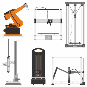
Pick and place systems come in various forms, each designed to suit specific applications and requirements.
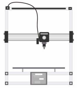
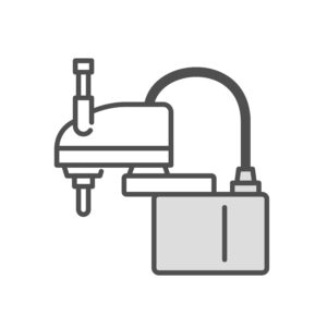
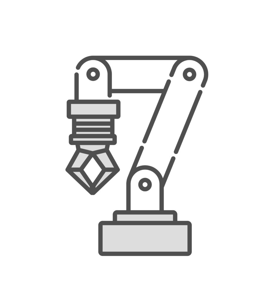
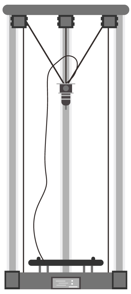
Several classes of pick and place robots are briefly introduced below.
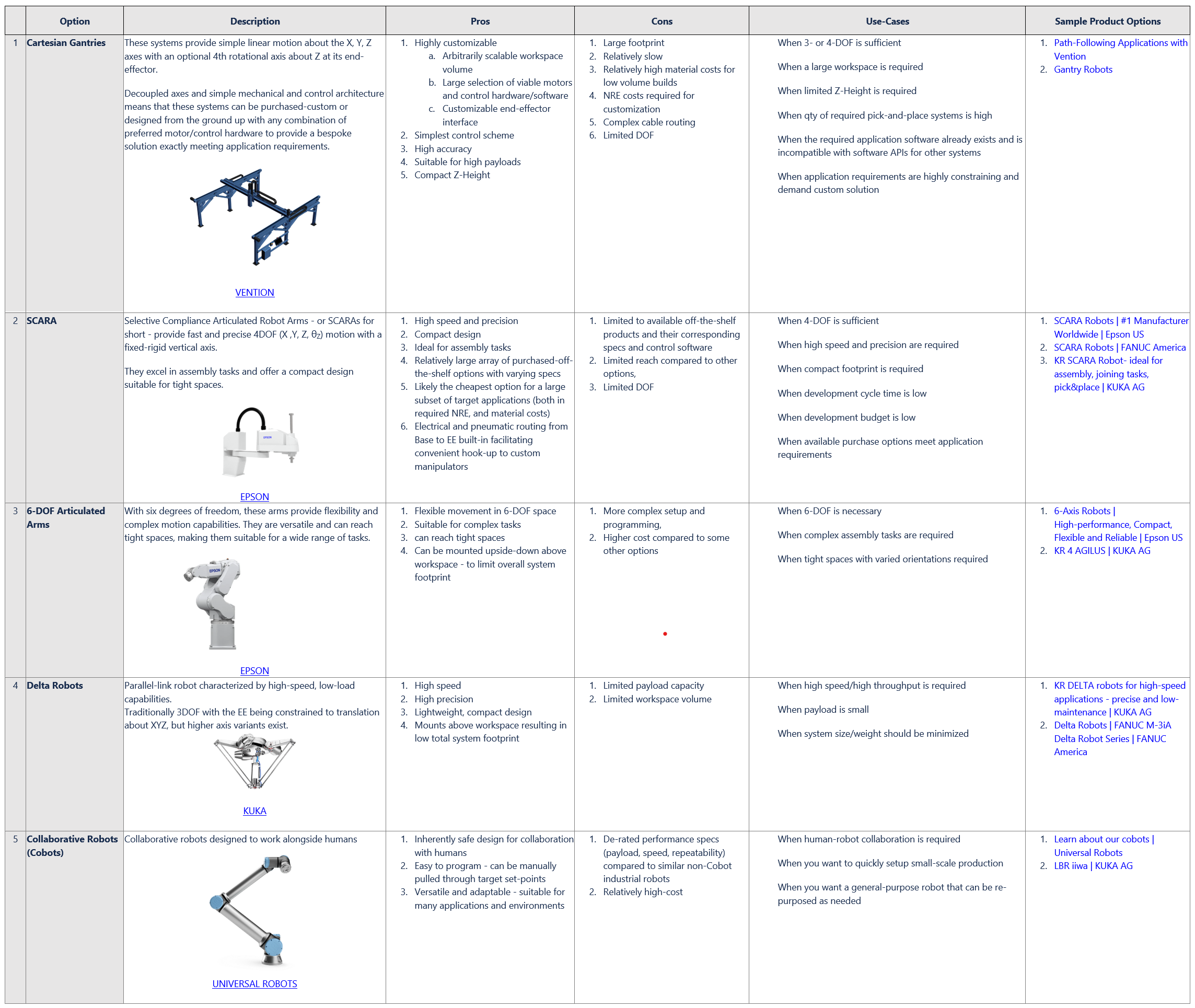
A more detailed overview of their defining features, benefits, limitations, use-cases, and available products can be found in the Selection Guidance Table further down in this whitepaper.
Application Requirements and Design Considerations
No two pick and place applications are identical – each being subject to unique requirements and constraints that dictate the design and selection of an appropriate solution.
Several key design elements are outlined below that should be taken into consideration and weighed against each other prior to developing your system.
|
Design Element |
Considerations | |
|---|---|---|
| Workspace Volume and Constraints |
|
What is the required working area and are there any spatial limitations that may impact the system’s layout and operation? The final link in the kinematic chain of a robotic system (and anything rigidly connected to it) is referred to as the robot’s end-effector. Each robot will have a workspace envelope specified about the robot’s origin defining the range and orientations that its end-effector can reach. For a simple XYZ Cartesian Gantry – this envelope will be a rectangular prism defined by the travel limit of each of its axes. A 6-DOF Articulated Arm will have a complex 6-dimensional constrained envelope describing end-effector orientation (θX, θY, θZ) at different XYZ locations in space: e.g. when the arm’s ‘elbow’ joint is straightened out, its ‘wrist’ will be at the maximum radius away from its base and the end-effector orientation-range will be significantly limited compared to when the arm is bent with the end-effector closer to its base. Is the workspace volume arbitrarily large? If so, a single custom-scaled Cartesian Gantry may be preferable compared to requiring multiple limited-range SCARA arms working in concert. Do the target pick and place locations exist on different work-surfaces? Then it may be advantageous to position a SCARA robot between those surfaces rather than having a Gantry straddling them. Is the path between each target location unimpeded or is navigation around/over interfering components required? The exact nature of these constraints may dictate that one solution or another is preferred. |
| Degrees of Freedom and Range of Motion |
|
How many degrees-of-freedom at the end-effector are required by the application? An unconstrained rigid body in space has 6 degrees-of-freedom (6-DOF): it can translate about 3-axes, DX DY DZ, and it can rotate about those same 3-axes, θX θY θZ The DOF of a robot’s end-effector, however, are constrained by the number and configuration of its joint-axes, and the relative range of motion about each of its joint-axes will dictate the absolute range of motion of the end-effector in space. Do all pick-place target locations have the same orientation along a shared horizontal plane? Then a simple 3DOF Gantry with minimal Z-range may be sufficient. Do the target locations lie along multiple non-parallel planes? (for example, if a flat component must be picked off a horizontal conveyor and re-oriented and placed against a vertical surface for processing) |
| Manipulator Design |
|
How will the robot interface with the world? In a typical pick and place system, a manipulator is mounted to the end-effector that is capable of interfacing with target environment or component features. The requirements of the manipulator should be considered when selecting a suitable pick and place system. How large must the manipulator be? The geometry of the manipulator must be taken into account to determine the new available working envelope for the robot’s end-effector and to evaluate interference zones. Does the end-effector require electrical or pneumatic inputs? Some off-the-shelf SCARA and Articulated arms provide electrical and/or pneumatic pass-throughs from their base to their end-effector to facilitate convenient connections to the manipulator, if needed. This can dramatically simplify the wire/tube routing design process compared to other systems lacking these features, (for example, a custom Cartesian Gantry), where special considerations for routing must be made such as cable/tube length, flexibility, service loops, slip-rings, etc. How many different geometric components/features must it be able to interface with? It is not uncommon for a single robot to have multiple manipulator tools to interface with multiple distinct component features. This can be readily accomplished by having multiple tools rigidly mounted to the end-effector but with each having some defined offset relative from the end-effector origin. By accounting for each tool’s offset, the robot can effectively index between each, with the consequence that each tool’s workspace volume will be offset or constrained in some manner compared to the end-effector alone. |
| Payload | What is the mass and moment of inertia of the payload?
The payload mass/inertia is the sum of those of the manipulator plus the component(s) that must be carried by the robot end-effector. The pick and place system must be rated to accommodate the necessary payload and inertial forces. Some pick and place system manufacturers(e.g. Epson) may spec a ‘rated’ payload in addition to a ‘max’ payload. It should be assumed that for a payload greater than the ‘rated’ spec, all other listed performance specifications (e.g. speed, acceleration, precision) will need to be derated. |
|
| Speed/Throughput | What is the required cycle-time for the pick and place system?
A pick and place robot is often a sub-system within a larger automated process. It is important to understand the total process throughput requirements (i.e. widgets processed per hour) to determine the maximum allowable cycle-time for the pick and place sub-system before it becomes a rate-limiting step in the overall process. |
|
| Accuracy and Precision |
|
What is the minimum required accuracy/precision/repeatability required by the target application? Although accuracy and precision (aka repeatability) are technically distinct quantities – it is common to see products specify only a single quantity (either accuracy, precision, or repeatability) defining the maximum expected position/orientation error of the end-effector across its workspace. It is important to understand the subtle differences in interpreting this specification for different pick and place systems:
A simple rule of thumb when designing the layout of your pick and place system is to preferentially locate the target pick-place locations comfortably within the arms workspace away from its limits or elbow-inversion points. |
| Safety |
|
Is the robot situated in a work environment shared by human operators? Any automated system with actuating components introduces safety concerns for operators in their vicinity, and provisions to prevent accidental injury should be taken in their design. Pick and place robots can be especially dangerous as they encompass multiple components that can move rapidly and forcefully across a potentially large workspace. Typical provisions for mitigating safety concerns of automated systems are:
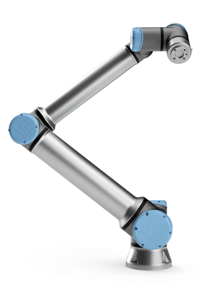
Does the robot have to be exposed and/or interact with human operators? Collaborative Robots (Cobots) are specifically designed for safely interacting with or operating in a shared space alongside humans. Cobots are typically operated with limitations imposed on their speeds and forces, and designed with either force sensors, or mechanics with software control schemes that ensure reliably safe operation in close proximity to humans. As such, cobots are realistically the only viable option for this scenario. |
| Controlled vs Uncontrolled Pick locations |
|
Are the pick locations for incoming components in known/well-defined locations and orientations? If the position and orientation of the incoming components are well known relative to the robot coordinate-frame – then control of the robot can effectively be run open-loop, blindly moving to defined pick locations and confidently aligning/interfacing with the components there without any additional provisions. Are the pick locations not well defined? If the incoming components are not in known/well-defined positions/orientations – for example, components being fed along a conveyor belt – then additional provisions are likely required to determine their position/orientation relative to the robot’s coordinate frame prior to interfacing with them, and those provisions may further constrain the selection of an appropriate pick and place system. Determining the necessary alignment information for incoming components can be accomplished in a number of ways depending on the application. An example approach might be to incorporate a presence detection sensor in conjunction with a vision system either mounted above the pick region or directly to the end-effector of the robot, in order to (for example):
Detailed considerations for designing an appropriate vision guidance system for a pick and place application fall outside the scope of this article – but further information and available solutions can be found within Cognex’s Product Suite: Machine Vision and Industrial Barcode Reading Products | Cognex |
| Schedule/Cost |
|
What is the planned development schedule – how much time is allotted for design? What budgetary constraints exist for material costs, build/labor hours, non-recurring-engineering (NRE) hours for this development? Schedule and cost are often primary driving factors in product design and development. It is important to have an up-front understanding of any budgetary limitations which may dictate the selection of a pick and place system and the design trade-offs that can be made according to the program budget and development timeline. What is the anticipated production quantity for the pick and place solution? For pick and place systems only requiring 3- or 4-DOF, an array of purchased off-the-shelf SCARA arms are available with varying specifications (see Epson), which, if suitable for your application, provide very cost competitive pick and place solution requiring minimal NRE to incorporate into your system. If the planned production quantities for your system are large, however, then it might be preferable to design a bespoke Cartesian Gantry tailored to your exact requirements since the material costs will scale down with volume and the increased NRE costs associated with its design may become justifiable when spread across many builds. |
Selection Guidance Table
*Click here to download a copy of the Selection Guidance Table PDF with links
Down-Selection Case-Study
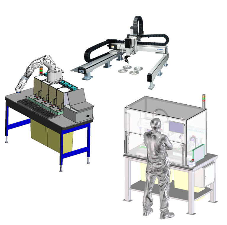
At Simplexity we have developed a sizable portfolio of projects with integrated pick and place systems and routinely go through the down-selection process to determine the most suitable system based on each project’s specific requirements.
In a recent project, our client requested an upgrade to further automate several existing processing stations within their production line that, up until then, required continuous operator involvement to load/unload thousands of palletized components per day.
There were several key application-specific requirements identified that drove this down-selection process:
-
Very constrained workspace – the pick and place system and 4x processing stations had to fit onto an existing workbench, on a crowded production floor, with no relief for expanding the footprint beyond the table edge
-
Safety – the existing workstation was immediately adjacent to other human operator workstations and had to be inherently safe
-
Accessibility – pallets of incoming (un-processed) components and outgoing (processed) ones needed to be installed and removed from the system by a human operator
-
Throughput – each workstation was to have four of the existing automated processing stations running in parallel. The pick and place cycle time target was set to maximize the up time of all four processing stations.
-
Software Control Architecture – each of the existing processing stations were monitored and controlled by separate instances of a previously designed PC application. The new work-cell was required to have a single software application running that could coordinate control of each of the four processing stations in addition to the pick and place robot and safety monitoring supervisor.
-
Cost/Schedule – this was a time-sensitive project – requiring that two of these new automated work-cells be ready within a few months of project kick-off in time for an impending production ramp-up.
After careful evaluation, we opted for an available off-the-shelf SCARA (Epson T6-B) due to its low cost, minimal required design-time to implement, and compact design compared to other alternatives.
The off-the-shelf solution available met the requirements while staying within budget, making it the ideal choice for our client’s application.
For a more detailed dive into the down-selection process and implementation details of this case-study see: SCARA Robot Design
 Conclusion
Pick and place systems are integral to modern automation, offering efficiency, accuracy, and versatility in handling various tasks. By understanding the available options and considering factors such as application requirements and budget, businesses can make informed decisions when selecting the right pick and place solution. For further reading and exploring specific options, reach out to reputable vendors and stay updated with industry trends.

