With time-to-market pressures often compressing design engineering cycles, being able to employ creative prototyping techniques to get through vital design hurdles is critical. Using a combination of CAD-based component selection, cardboard modeling, and software and hardware simulations, a complex robotics solution was designed and debugged within an accelerated timeframe — all before needed parts had even been received. Read on to learn more about the project.
We were asked to add a robot to a tool to reduce the workload of operators. The tool has 4 stations in which a specific part is processed. These parts are provided in input trays and after processing in one of the 4 stations they are placed in output trays. Moving the parts from the input trays to the stations and then from the stations to the output trays was to be the task of the robot.
This article describes the process to quickly move from initial robot selection to the final integration of this Mechatronic tool by using models of increasing complexity, cost and fidelity, starting with a cardboard model.
Robot Selection in CAD
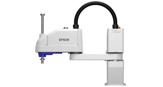
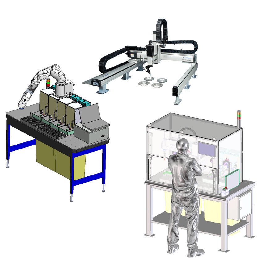
Several types of pick-and-place tools were considered (see Figure 1), amongst which articulated robots and gantries. Importing the models into CAD simplified the task of comparing different configurations. The combination of limited space, price, and robot availability lead to the selection of a 4 joint SCARA (Selective Compliant Assembly Robot Arm) robot: a 2-joint arm for XY movements, a vertical move and rotational move for orientation and placement of the object.
From CAD to Cardboard
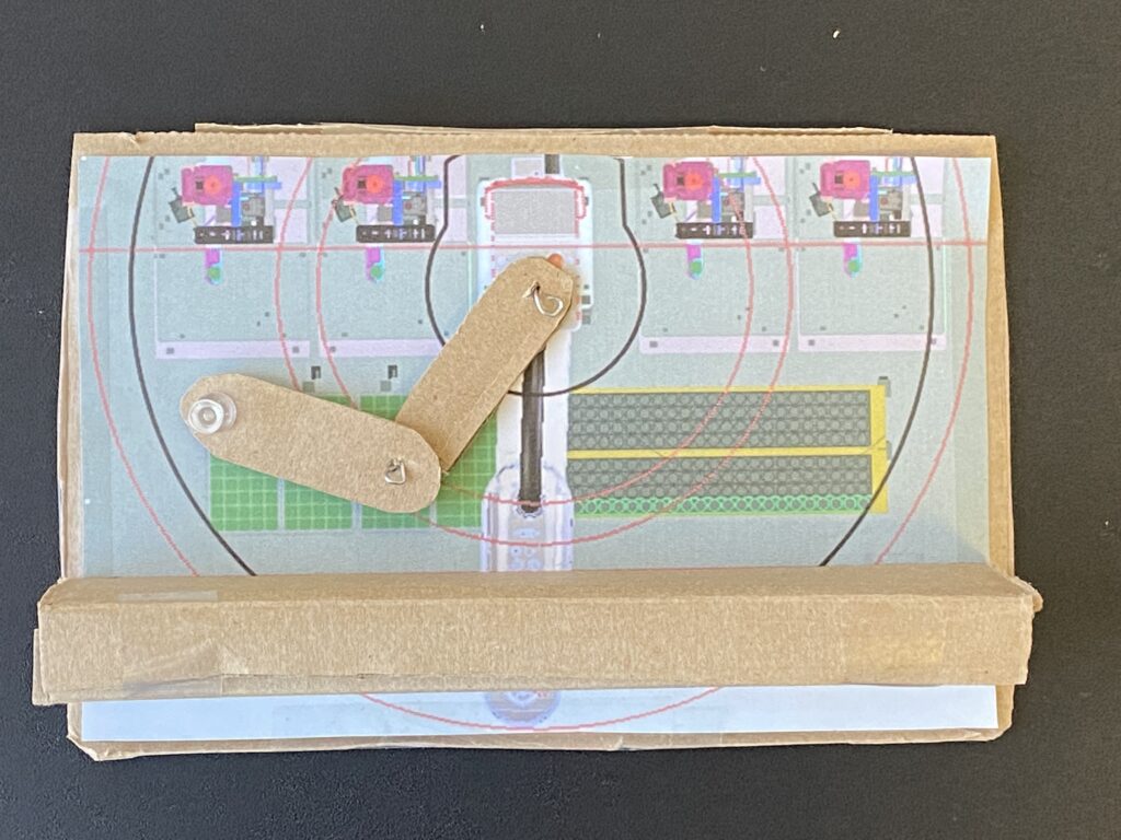
The choice for a specific SCARA robot and its placement in the middle of the 4 stations was heavily driven by space limitations: the complete system had to fit on a 5’ x 3’ table. One of the downsides of this solution is that the arm cannot move from left to right in one big swoop and it was clear that the impact on cycle time needed to be investigated. To get a better understanding of the (im)possibilities of moving its arms around in such a confined space, a small cardboard model was made, as depicted in Figure 2. Within hours, this allowed us to get a feel for the movements, the approximate robot speed, and the types of moves that were needed. The background drawing of the model in Figure 2 is a screenshot of the CAD design with the imported EPSON robot model, which included not only the robot but also the workspace and range of the robot’s end-effector.
The small workspace required the robot to perform an elbow invert from (what is known as) a LEFTY-mode, where the first and second joint of the robot look like the arm of a person who writes with his left hand, to a RIGHTY-mode, and vice versa.
OUTCOME: One of the choices that was made at this point is that all activities on the left side of the tool would be done in LEFTY-mode and conversely all actions on the right side of the tool would be done in RIGHTY-mode. This would simplify the administration of when the elbow-invert needed to be executed. Analysis shows that if the stations are serviced in order from 1-4, an average of 2.5 elbow-inverts are needed for each product that is processed.
From Cardboard to Simulations
EPSON’s RC+ a rich simulation environment that includes 3D animation of all robot joints, the execution of scripts to simulate real-life moves and virtual walls to detect collisions. Within a day the first series of simulations were performed of processing a full input tray, while evaluating items like average cycle time and collisions.
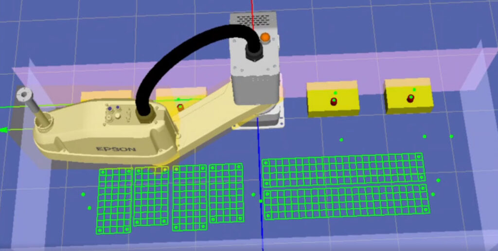
See video below.
OUTCOME: Using this simulation tool, the placement and reach of the robot were confirmed and waypoints were defined which were used for the elbow-invert moves. Further experiments confirmed that the cycle time could be achieved, even at the top of the robot’s speeds.
SCARA simulation
From Simulations to Hardware
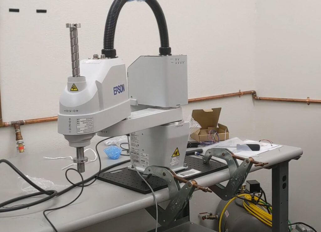
All the work described above was performed while the robot was ordered and being shipped. Immediately after the delivery, the development switched from simulations to using the actual hardware, which was used to implement functions to abstract the elbow-invert moves. Using the knowledge from the simulation scripts, abstraction layer software functions were defined and written in a matter of a couple of days. These functions execute moves to the input- and output-trays and the 4 individual stations without having to worry about whether to perform an elbow-invert move or not.
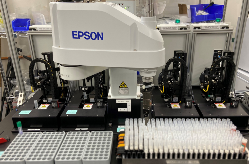
Figure 4. Before installing the SCARA robot in the tool, it was used to develop high level move sequences like ‘elbow invert’.
Final Product
During the assembly of the tool with the robot, the higher-level tool control software was modified to work with the mentioned abstraction layer functions and within days full pick-and-place cycles were executed.
Figure 5 shows the final embodiment of the design with the 4 stations in the background.
One change that had to be implemented to speed up the cycle time was to use (so-called) Move-moves instead of Point-To-Point (PTP)-moves. The latter move performs linear interpolation between the start location and the end location of the end-effector, which made it easier to avoid enclosure collision. However, this PTP-move turned out to be limited to the lowest speed that can be achieved anywhere in the end-effector’s range: imagine a straight line move where the end-effector is close to the SCARA robot’s base. For this move, the first joint at full speed will result in a lower speed than that of the end-effector during a move with the arm fully stretched out. The maximum PTP-move speed is clipped to the achievable end-effector speed while close to the robot’s base. Instead of the PTP-move, a set of weigh-points were defined, and the Move-move was used in which the robot executes the move in the shortest time possible, not worrying where the end-effector is during the move. This results in arc-shaped moves, and when using several weigh-points the movements were still guaranteed to stay inside the enclosure.
The cycle time was still somewhat slower than anticipated due to issues like the need to reduce the maximum acceleration to limit excessive shaking and the fact that opening and closing the gripper and scanning a barcode took more time than anticipated.
A possible solution to the cycle time issue would be to reduce the number of elbow inverts which account for approximately 40% of the cycle time.
OUTCOME: Even though the robot is an off-the-shelf component and came with excellent simulation software, getting to know the software interface and robot behavior might lead to surprises. If possible, spending 1 or 2 days in training when starting with a new ‘machine’ would have easily offset time spent debugging and ‘back and forth with the supplier’ emails.
Back to the Cardboard
Upon inspection of the cardboard prototype, it became clear that about 105 of the 200 cells on the input tray can be reached in both LEFTY mode and in RIGHTY mode. For the output trays an estimated 112 out of 196 cells can be reached in both modes. This meant that a product on the right-hand side of the tool could be moved to the output tray in RIGHTY mode and the next product could be picked up from the input tray (see the arm orientation in Figure 6) to the station in RIGHTY mode. This results in a reduction of the number of elbow inverts from 2.5 to 0.5 per product, at the cost of a more complex administration.
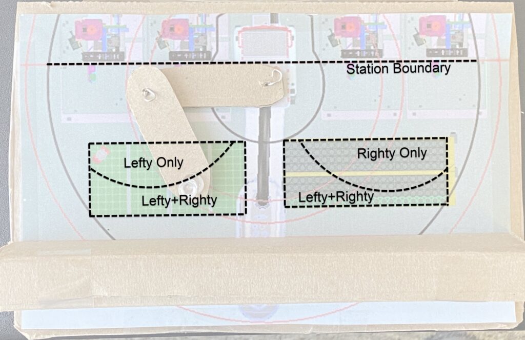
OUTCOME: Measurement on the real hardware, in combination with analyzing our cardboard model, gives high confidence that an implementation of (what we affectionately call) an ‘armpit move’ will result in achieving the cycle time requirement.
Conclusion
The moral of the story: don’t underestimate the power of a pair of scissors and a piece of cardboard. There is something really powerful in having ‘hardware’ on your desk to play with, stare at, and show others what you’re thinking.
In our case it allowed us to speed-up and de-risk the mechatronics integration of a pick-and-place unit into an existing tool by not only using CAD and Simulation tools but also using a little cardboard model to ‘get going’. The combination of these tools allowed for early decision making and debugging long before the final integration of the robot in the tool.

