CASE STUDY: AUTOFOCUS MODULE
Quiet motion with infinite bearing life.
When you need 200 microns of precision motion why use traditional bearings and rails?
As feature sizes decrease, camera based imaging systems need auto-focusing mechanisms to produce good data. Because travel distances are typically in the 100 to 1000 micron range for auto-focus applications, traditional linear bearing or guide rail based solutions are bulky and expensive.
Our client challenged us to develop a compact, high precision motion stage for their new product line.
What We Did
Simplexity developed a prototype focusing module that replaced traditional bearing rails with a flexure (aka a compliant mechanism). The flexure consists of parallel plates that act like a four-bar-linkage over a limited motion range. The motion range has both linear and non-linear regions. Finite Element Analysis allowed us to accurately predict motion in the linear region and a lookup table corrected the remaining non-linearity.
We achieved a highly compact mechanism with infinite bearing life that was roughly 50% lower in component cost.
THE PROCESS
Concept Development
Applying our Simpler is Better design philosophy, we developed several different concepts that replaced traditional linear guide rails with a compliant four-bar linkage. We explored several different types of actuation methods using the compliant linkage concept as both a guide-way and as a method to provide a bias force.
Hardware
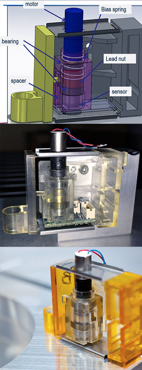
In the concept shown, a miniature DC motor drives a lead nut up and down. The motor and lead screw are stationary while the lead nut, coupled to the camera housing, provides the auto-focus motion.
Good concepts only become good solutions when supported by detailed engineering work. We ran extensive finite element analysis (FEA) to develop the details supporting this concept. The FEA work helped identify and deal with non-linear portions of motion, to design for infinite fatigue life, and to assess camera stability in the presence of vibration input.
Firmware
Embedded motion control was a key ingredient. The closed loop servo in this design includes a DC motor, a lead screw and a magnetic sensor located directly below the lead nut. As the lead nut advances, the magnetic sensor encodes the position change.
While lead screws are inherently accurate positioning components with low linearity error, in order to meet the tight tolerances in this application, we further improved the reliability by adding a lookup table to manage non-linearity effects.
Generating the lookup table parameters means using a reference interferometer to characterize each module in production. For some applications, the additional manufacturing step would be problematic, but in scientific imaging, high performance requirements dictate creative solutions.
The resulting camera autofocus module is more reliable and lighter weight than existing solutions because the mechanics are developed to optimally meet the payload and travel distance requirements. Plus it had a significant result on the bottom line, with a 50% Bill of Materials cost reduction over traditional systems.


