There are typically a number of considerations when choosing whether you want to use a stock gear or to design a custom gear. Two of the key considerations are cost (which is affected by opportunities for simplification and volume of parts to be produced) and performance.
COST
Cost has many components. The easy one to measure is the actual part cost and is typically the primary cost element considered. Also important are the cost of the engineering design & qualification, part specific tooling, part packaging, shipping, inventory and production line or assembly impacts.
So how can choosing a custom gear save money?
Once the product reaches the volume threshold where specific part tooling can be justified, all sorts of opportunities open up for the designer. Typically the largest cost savings is from the ability to integrate components or features into a single part. This will save on part costs but can also have a large impact on inventory and assembly costs.
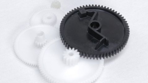
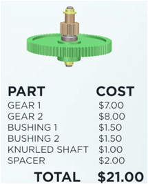
This can be best explained by looking at the example of a cluster gear that I custom designed. During prototyping, I had to buy two stock gears, make a custom knurled shaft, a custom spacer, and buy two off-the-shelf bushings. If we had taken this design to production, this assembly of six parts would have cost $21.
If we were only producing a few hundred units, it would have made sense to stick with this design utilizing the off-the-shelf gears. However this customer predicted volumes around 10,000 per year with a product life of at least 5 years.
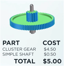
For the custom design, we integrated the two gears, the spacer, and the bushings into a single injection molded part. We chose a material that gave the gear and bushing performance that allowed for this simplification. We were also able to eliminate the knurls on the shaft. This custom assembly of 2 parts cost $5.
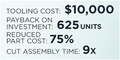
The cost for the injection mold was $10,000. This yielded a breakeven point of 625 units and reduced the per-unit cost by over 75%. Due to the part integration and simplification of the assembly processes, the assembly time was 9 times faster.
This gear is just one of five from the complete gear train. The overall cost savings for the entire gear train was more than half a million dollars in the first year alone, even accounting for the cost of tooling and engineering.
In addition to the cost savings we were able to optimize each gear pair for a number of performance parameters. For this design the most important parameters were strength and efficiency.
PERFORMANCE
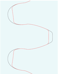
Designing a custom gear gives opportunity to improve the performance of the gear train. Most stock gears are “cut” using standard AGMA or ISO non-full fillet root tooth forms. In the figure below, I compare the tooth shape of an AGMA hobb depth tooth form (red lines) with the shape of a PGT3 tooth form (black lines). Noticeable differences are the shape of the root area (PGT3 has a full fillet shape) and in the overall tooth length (PGT3 is much longer).
Stock gears typically have limited choices in areas such as: tooth form, quality, tooth counts, pitch/module, pressure angle, helix angle, face width, hub shape & size, materials, center to center distances and the allowable tolerances for the center to center distance.
Custom designed gears can allow the designer to overcome these limitations.
Tooth form: The designer can pick the ideal form for the particular design and then fine tune to match the product needs as needed. This is applicable to both molded gears or to machine cut gears. Some standard problems and their custom tooth profile solutions are:
- Stress concentrations use full fillet roots
- Tooth to tooth impacts create tip reliefs
- Center to center distance tolerance variations elongate the tooth forms
- Noise increase the contact ratios or change materials
- Gear pair strength balance tooth thickness across the gear pair, which is especially important with gear ratios > 1.5X
- Product life add or change lubrication to lead to less wiping or galling and improve pair efficiency
Quality: Typical stock gears have AGMA quality ratings of Q5A to Q7A. Gears made with custom tooling can achieve quality levels of Q10B or better.
Tooth count: Almost any number of teeth can be specified onto a custom gear, resulting in a gear ratio that might not be available with stock components. From a wear or life standpoint, you might also want to choose gear pair tooth counts that keep the same teeth from always engaging one another. This distributes wear, dirt, and lubrication evenly across all the gear teeth involved. The best way to do this is to choose the number of teeth on a gear to be prime (or at least co-prime) numbers.
Pitch/Module: Utilizing non-standard gear pitches (the number of gear teeth per inch) can allow for unique center to center distances. This can be done with either cut gears (purchase of a custom hob for example) or wire EDM cut inserts for injection or powder metallurgy molds.
Pressure angle: Typical industry standards of pressure angles (the angle through which forces are transmitted between meshing gear teeth) are 14.5o and 20o. Each have advantages and disadvantages. Being able to fine tune the pressure angle gives the designer another variable to use to optimize the design of the gear. For example while small pressure angles are better for improved contact ratios on large center to center variations, larger pressure angles >20o are better for improved tooth strength.
Helix angle: For helical gears (gears with curved teeth) custom designs allow the engineer to specify the helix angle. By both increasing the helix angle and widening the face width, the contact ratio increases, which reduces noise and improves strength.
Face width: In general, increasing the width, or thickness, of the gear increases strength. However, there are limitations to consider as the mesh of very wide gears can be affected by mount or shaft deflections.
Hub shape/size: With a custom gear, designers can optimize the method used to “attach” the gear to the rest of the system. This might be by incorporating the bushings as part of the gear, creating unique hub shape or size to engage a shaft, or designing a special shape to directly engage with other components in the system.
Materials: Stock gears typically have limited material choices. The most common plastic materials are unfilled acetal & nylon. Typical metals are steel, cast iron, brass & bronze. One opportunity to optimize plastics is to blend lubricants into the base plastic to eliminate the need to add external lubricants. Lubricants can collect dirt or be improperly applied which can limit their effectiveness, especially over time and as they are exposed to different environments. Acetal can be blended with Teflon and/or silicone to gain efficiency in the gear mesh without the limitations of external lubricants. Adding glass or carbon fiber to the plastic can improve strength or conductivity. Other materials can be used when specific material compatibility is required.
DESIGN TOOLS
At Simplexity Product Development, we use a custom developed gear design tool which has been proven out with hundreds of custom gear designs. This tool allows us to fine tune a large variety of attributes in the gear pair with ease. As the tool has been developed in-house we also have the ability make tool modifications to easily address customer specific needs.