What is the correct (or best) motor to use in a motion control application? Given the myriad choices of type, size and performance it should not be surprising that there is no simple choice of motor that supplies the answer to that question.
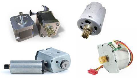
When considering a motion control design choosing the correct motor type and size can seem to be an overwhelming task. Typically, there are three basic motor types to consider: Stepper Motors, Brushed DC Motors, and Brushless DC Motors. In a given size there exist choices in magnet material and winding configuration. Indeed, custom windings are often the norm.
You must be wondering if there is a process that can help make sense of all that information and assist you in choosing the best motor for the application. Fortunately, there is! At Simplexity we call this process “Motor Sizing”. I’ll talk more about motor sizing but first let’s develop an understanding of the various motor types.
STEPPER MOTORS
Stepper motors get their name from that fact that as the motor is commutated (phase coils driven in sequence) the output shaft rotates a set angular amount. As a result, the step size, specified in degrees, is a key specification for these motors. Common step sizes are 0.9°, 1.8°, 7.5°, and 15°. The style of construction used to manufacture the motor has a direct influence on both the step size and the maximum operating RPM.
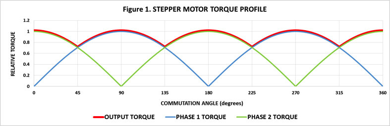
Figure 1. Illustrates the torque profile for a bi-polar wound stepper motor commutated in full-step mode. Note that the individual phase torque profile is sinusoidal and it is the overlapping of these individual torque profiles via commutation that provides for a more consistent torque output. There is a considerable amount of torque ripple that results in noise and vibration. The torque ripple can be minimized by using more complicated commutation techniques. Stepper motors are usually most suitable for the low to mid RPM range of operation.
Stepper motors have a fixed outer stator and a magnetic rotor. They are a brushless design as the rotor is pre-magnetized and only the stator is electrically connected. Theses motors are manufactured in a “tin can” style and a “laminate” style. The tin can style use stamped sheet-metal components to form the stator halves. These components nest around pre-wound coil bobbins. Construction is simple and low-cost. One draw-back is that tin-can motors are usually only available in the largest step sizes. Other disadvantages when compared to the laminate style are lower maximum step rates and efficiency. This is primarily due to looser assembly tolerances and the need to use less magnetically efficient steel in the stator stamping process.
The laminate style motors have the stator constructed using stamped steel laminations similar to those found in transformers. The stack height can be extended in increments to form different lengths of stators. Once the stator is assembled the coils are then individually wound onto it. The better magnetic qualities of the stator steel and tighter assembly tolerances result in stronger, faster and more efficient stepper motors. They cost significantly more than the tin-can style but often feature niceties like ball-bearings and the ability to accept shaft encoders.
Steppers motors have a reputation as being “easy to use” as they typically do not require an encoder for position feedback. As well they can be driven simply with transistor switches or H-bridges without PWM control. However, in practice there is often a high price to pay when opting for the “easy” approach. In order to work open-loop (no encoder) and with simple drive circuitry the motor is often over-specified in its torque & speed capabilities. The goal is to make the motor’s dynamic characteristics predominate the system behavior which helps to insure that the motor can be relied upon to do as it is commanded.
The problem with this simple approach is that too often the end result is a noisy & vibration-prone system. With further effort and more complex driver topologies many of these limitations can be overcome. The advantages of being brushless, running open-loop and holding position while de-energized often make the extra effort worthwhile.
BRUSHED DC MOTORS (DC)
Brushed DC motors have the magnets located in the stator and it is the coils built into the armature assembly that rotates. Unlike stepper and brushless DC motors, DC motors are self-commutating due to the geometry of the brushes and the commutation ring located on the rotor shaft. The phase coils are automatically switched in the proper sequence as the rotor turns. In simple terms these motors produce a torque that is linearly proportional to the motor current. They are easily driven via an H-bridge and PWM control.
The armature is built using laminations like the laminate stepper and so benefits as well from the improved magnetic properties they offer. An important difference is that the laminate stepper has the coils wound on the inside of the stator which is difficult and time consuming while the DC motor armature has the coils wound on the outside which is much easier to do. DC motors typically have formed metal cans for the outer stator assembly. Although the steel types required for the forming process are not as efficient as in that in the armature this has a negligible effect on motor performance as all of the magnetic switching takes place in the armature.
Brushed DC motors can be used open-loop but the results are often not satisfactory. Run in a closed-loop mode they can offer a wide range of motion profiles. As the torque output is both smooth and tailored to provide only what is needed the resulting motion is smooth and mechanism operation is quiet. DC motors can be used from very low to high speed operation.
There has been a great body of work in the area of linear & control system analysis using this type of motor. As a result, there are established techniques for proving design margin and stability in designs using these motors. This can be of particular value in mission critical or high volume applications.
When compared to a stepper motor system a well-designed DC servo motor system is very often less-expensive while offering higher levels of performance and perceived customer quality.
BRUSHLESS DC MOTORS (BLDC)
Brushless DC motors behave somewhat like a blend between stepper motors and DC motors. They have the advantage of being brushless and thus offer long operating life and electrically quiet operation just like a stepper motor. Using sophisticated control schemes they can be treated as a linear torque source like a DC motor. With the proper feedback BLDC motors can be utilized from the low to the extremely high RPM ranges.
The BLDC motor can be built with a fixed inner stator that is constructed like a DC motor armature. The outer rotor contains the magnet ring. Outer rotor designs such as this excel in high speed operation and are simple to build. The inner rotor design has the stator constructed much like that of the laminate core stepper motor and the magnet is the rotor. While typically offering less speed performance an inner rotor BLDC dissipates heat more easily.
For proper operation a BLDC motor must be commutated at the correct point in its rotation. This requires feedback of some form. Historically this has been done with Hall sensors built into the motor. The motor coils are commutated based on the Hall sensor output values. Recently there are control schemes that rely on measuring when the zero-crossing of the sinusoidal Back Electro-Motive Force voltage, (BEMF) occurs in the individual coils. There are integrated circuits available that can perform this measurement and do the commutation automatically. Some vendors offer BLDC motors with these circuits built in and thus offer operation much like a DC motor. Depending on performance requirements there are even more sophisticated control schemes available.
SO HOW DOES MOTOR SIZING HELP ME CHOOSE WHICH TYPE OF MOTOR TO USE?
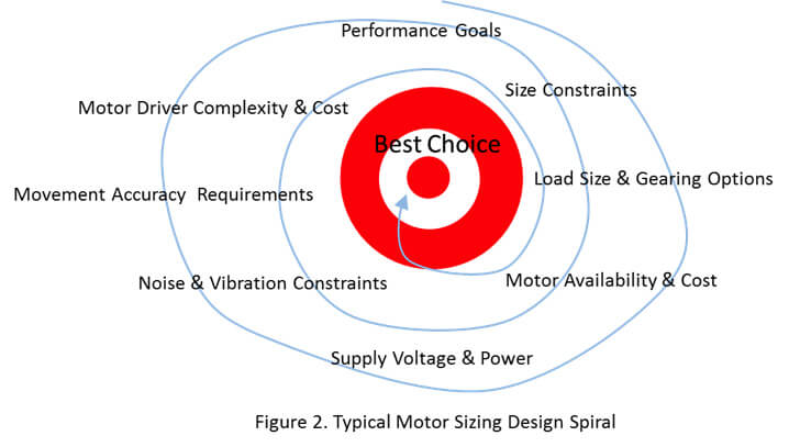
Motor sizing is the process a motion systems engineer goes through to select a motor for a given application. It is a systems level analysis in which the engineer will iteratively evaluate the available motor choices against the application’s goals and design constraints. In essence the process is to follow an engineering “design spiral” to achieve the desired outcome of having a servo motor system design that meets the application requirements. Figure 2. Illustrates a typical design spiral for this process.
WHERE DO YOU START?
A good starting place is to identify the goals and design constraints for the application. These may include:
- Total servo system cost
- Application size constraints
- Motor availability & cost
- Minimum available supply voltage
- Maximum allowable supply current
- Driver circuit complexity & cost
- Average & Peak power supply limits
- Driver IC current and power dissipation limits
- Servo acceleration and velocity requirements
- Servo accuracy requirements
- Load friction and mass
- Noise & vibration constraints
At this point enough information may be available to make an informed choice of motor type for this particular application. Maybe the noise and vibration constraints rule out using a stepper motor. On the other hand, it is possible that the operating-life goals dictate a brushless solution. If you cannot make an informed choice at this stage you need to iterate through the design spiral with each motor type so that you can compare the outcomes.
As you do this you will identify design tradeoffs across the system. For example, you might find that the specified power supply output power is adequate overall but a different voltage level would result in a lower system cost. You should note that each motor type requires unique design and debug capabilities in order to implement a good design. Your ability to provide these capabilities should be taken into account when analyzing the system level trade-offs.
Eventually suitable candidate motor options will be identified. This is the first step in the motor sizing process. Now the motion systems engineer can begin a detailed analysis of the options identified and begin to consider motor frame sizes, winding parameters and control topologies. I will be discussing those topics in future articles.